Antennas

NEW WEBSITE

After months of mucking about and testing, I FINALLY pushed the new site out last week.. Only 3 bugs found so far; 1) Netherlands didn’t have any shipping options and  2) USA between 12kg and 20kg couldn’t get a shipping quote! All fixed now and it seems to be working.

Right now, we’re sorting this old site out and upgrading to latest versions of PHP etc.. The main shop is now over at dxcommander.com

Quarter Wave -vs- 5/8ths Wave Vertical

q-wave-vs-5-8th-wave

Compare Red 5/8th -vs- Blue W/wave

Anyone who has mucked about with verticals will no doubt have worked out that a full-sized quarter-wave for the 40m band, more or less tunes up for 15m band.

It wasn’t until my entry in IOTA Contest this year that I convinced myself that they are not a cloudburner (as many people suggest) but compare favorably with a quarter-wave, even producing more gain by 2 dB at 10 degrees above the horizon.

OK, so 2 dB isn’t a huge gain, but hey – it’s free. Take it when you can!

Don’t forget, you can do the same for 10m band too by making an element 6.83m long and folding it back a further 1.11m (for 28.5 MHz). So you’ll need nearly 8m of wire. Don’t forget, that’s insulated wire!

Quick SWR Calculator for Vertical and Dipole Ham Radio Antennas

Here’s a really simple way of double checking how to much to trim your antenna elements.

You only need to type in the numbers in the Cyan boxes.

  • For Dipoles: Cut / Add the result to each leg
  • For Verticals: Cut / Add result to your vertical radiator

Just type in where it is resonant right now – then type in where you would like it to be resonant and the spreadsheet will auto-calculate the trimming.


* Thank you to Aubrey (AubsUK on YouTube) for the Online version below:

Resonant Now

Frequency that gives a perfect resonance
 (MHz) 
WaveWavelength of the resonant frequency
¼-WaveQuarter wavelength of the resonant frequency
LengthTotal length of all elements for the resonant frequency

Aiming for

Target frequency for perfect resonance
 (MHz) 
WaveWavelength of the target frequency
¼-WaveQuarter wavelength of the target frequency
LengthTotal length of all elements for the target frequency
 

Adding 80m to DX Commander All Band Vertical (9-bands 80m through 6m)

Regulars will know about the DX Commanders very cool results which are now filtering through in real world successful contest scenarios.

My own issue is that I needed just one antenna that would deliver an all-band solution, certainly for the contest bands of 40m, 20m, 15m and 10m – but I also needed 80m in the mix too.

My holiday home has a very compact small garden so the option of putting up a dipole for 80m is out the question, but modelling suggested than exchanging the 30m element for an inverted L for 80m should work.

The 80m element therefore starts vertical, like all DX Commander elements and turns a sharp corner at 6.9m above ground and droops down for around 13m or so, hanging over a bush at around 3m off the ground. Probably not perfect but perfectly adequate to score 44 QSOs inside an hour on the Saturday eve of the IOTA contest. That score includes 16 different IOTA multipliers, certainly a wide spread around Europe.

Continue reading

Software Modelling your Vertical antenna ground radials with MMANA

I’ve been scratching my head for years how to model an appropriate ground with my ground mounted Vertical Antenna radials.

I’d like to thank Sigi, DG9BFC for clearing this up for me.

HOW TO:

NOTE: I like to draw a small feedpoint in all my HF antenna models, like a 5cm length of wire where my “source” (coax) is connected to. Particularly useful for fan dipoles and for making other adjustments. I’ve left that part out for simplicity on this How To since I’m trying to make this super easy.

Continue reading

DX Commander now shipping to USA / Canada / Aus

After much research, I’ve managed to get the price to under £30 for USA, an additional £10 for Canada with Russia and Australia incurring extra costs. I’m doing this shipping at cost folks via a tracked parcel. You can buy shipping cheaper – but with horror stories I’m afraid.

  • Still a hugely economical antenna for what you get.

PS Postage for USA is only £30 using MyHermes for delivery to OCS in UK and on to United Parcels Service for local delivery in USA.

Experience is suggesting that due to the low price, no customs or duty should be paid when it lands your end for most countries (although I can’t guarantee that – although my shipping people tell me it’s under the threshold).

Start here:

https://www.m0mcx.co.uk/store/products/dx-commander-premium-build-hf-multi-band-vertical-system/

Vertical Antenna – How many Ground Mounted Radials Do I Need

I’m often asked this question and after 5 years of development, I think I finally have the answer thanks to both real-worl experience and the work that Rudy Severns, N6LF did in a controlled scientifically based experiment.

6b4a5492

Read the PDF document on this link:

Raised Radials are a completely different kettle of fish. These are tuned to the frequency i question and can give varied results.

PS – Another superb read for the very clever folks is here:

Good luck!

M0MCX Banana Antenna – an end-fed choke sleeve resonant feedline T2LT antenna design

A new document fully documenting the design of the Banana Antenna has now been released entitled, “Banana, a Half Wave End-Fed Choked Coax Antenna”.

banana-antenna

Banana Antenna

Antenna can be known as – and is similar to:

Sleeve Dipole / Flowerpot Antenna

The Sleeve dipole has traditionally been used by VHF antenna designers by sliding an external metal sleeve over the coax and connecting the sleeve to the braid of the coax so that the antenna appears to be centre-fed with an outboard “sleeve”. Some commercial CB antennas are also made this way. Continue reading

20m band End-Fed Choked Coax Dipoles (T2LT)

WARNING: This post has been replaced with the following analysis and design:

Banana Antenna Design May 2017

– – –

The Resonant Feedline Antenna is also known as:

• Sleeve Dipole (& Flowerpot Antenna)
• Resonant Feedline Dipole (J Taylor, W2OZH)
• Tuned Transmission Line Trap, T2LT (CB folks)

For more about common mode chokes, see this article:

Pictures of this experiment follow including the 10-25 MHz >8K choke follow.

75 ohm to 50 ohm transmission line matching coax stub

Coax Transmission line coax stubs are frequency dependent. Making a stub for one frequency means it WILL NOT work for another frequency. My example is for a 20m Resonant Feedline Dipole, sometimes called a Sleeve Dipole or Resonant Coax Dipole or Tuned Choked Coax Dipole.

So you have an approx 75 ohm impedance antenna and you want to get the best match you can. Take the wavelength of the frequency, multiply it by the velocity factor of your 75 ohm matching coax and multiply again by 0.0815.

For example.

14.225 MHz = 21.089 metres
21.089 * 0.66 (what ever your velocity factor is) = 13.19
Multiply 13.91 * 0.0815 = 1.134m

Therefore, your transmission line coaxial transformer will be 1.134m long which is apparently about 29 degrees around the 360 degree circle.

Data found here: PA0FRI page.

Finally, I discovered MANY pages on eHam and QRZ forums of people asking the same question but most answers are with people answering questions which were not asked – or giving advice how to fix the antenna, or live with it. Why Americans need to argue the toss when others just need answers beggers belief 🙂

40m compact fan dipole for 40, 30 and 20m bands

One of my aerials has just come down in the wind, a 40m compact dipole arranged as an inverted V with the ends coming down as far as the 6 feet fence height.

My garden is about 15m wide (actually it’s 51 feet wide, so a whisker over) however it’s too small to fit in full-sized flat-top dipole but an inverted V works well. Whilst you are at it, why not add in elements for 30m and 20m and have three bands on one feeder?

40-30-20m-fan-dipole

Width of this antenna is 15m. You can make it smaller to suit.

I have designed this antenna to be a flat top with droopy legs. The centre will be held up with a very sturdy aluminium scaffold pole with a 4.6m sailboard mast sleeved over the top. The aluminium mast will cross-bolt to an already installed steel scaffold bar already concreted in the ground. Bottom line is that I should achieve around 10m in height (30 feet or so).

Continue reading

DX Commander pre-production testing all-band vertical

BuyNow[EDIT] This is a very old post from about 2018..

The shop is on the link to the right, else the VERY OLD article is below:

40m-featured-image


I finally found some time this year to pull all the components together to test out in a real-world setting, the idea of using multiple elements on a single vertical fibreglass pole to achieve very good SWR and radiation patterns.

The problem with verticals is than in the main, people need either ATUs or they use that awful UNUN business with a single radial. The 9:1 UNUN business is just inefficient and the only way to to use an ATU effectively is at the feedpoint, not at the rig-end due to the severe losses.

A feedpoint ATU is expensive and generally requires a 12V power source. And long verticals have awful radiation patterns beyond 5/8th of a wavelength.

So the only way to reliably install a vertical and dispense with any worries about SWR and power handling is to build a mono-bander.

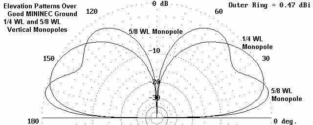
Regulars will know that I’ve been playing with the idea of adding separate elements to a 40m vertical mono-bander to add in the odd frequency, say 20m – but the interaction between elements can cause impedance issues (read SWR).

With development, I’ve discovered the optimum spacing between elements to achieve pure quarter-waves on 40m, 30m, 20m, 17m and 12m. It happens that the 40m vertical will resonate on 15m for excellent very-low radiation patterns and with the addition of a shorter-then-normal 10m element (around 2.6m in length) one can get radiation with a regular quarter-wave pattern, although the idea of using a ground-mounted vertical for 10m is slightly off-putting. There are other methods to get good radiation on the 10m band.

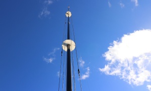
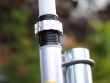
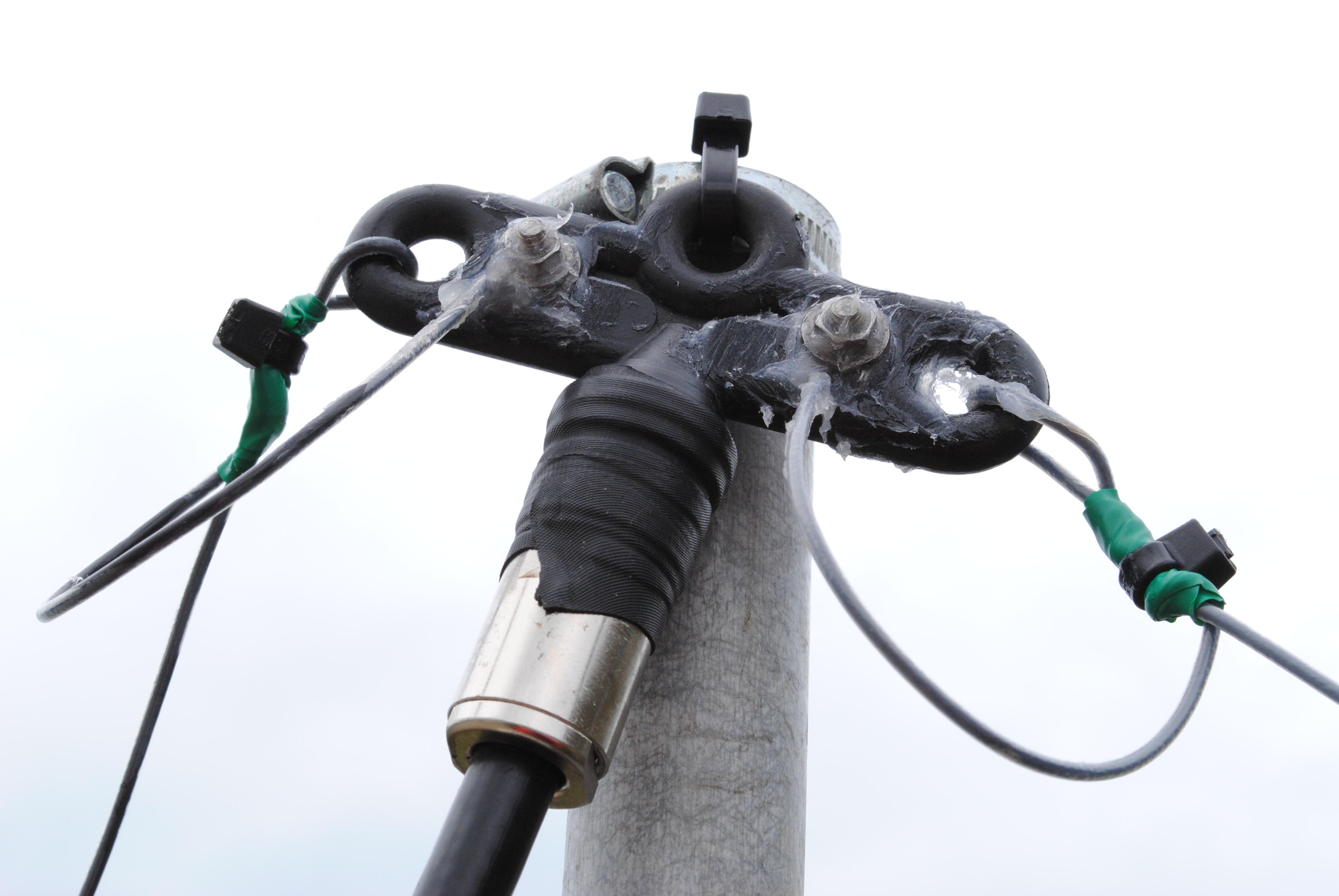
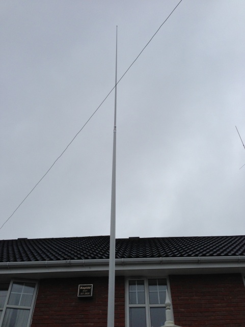
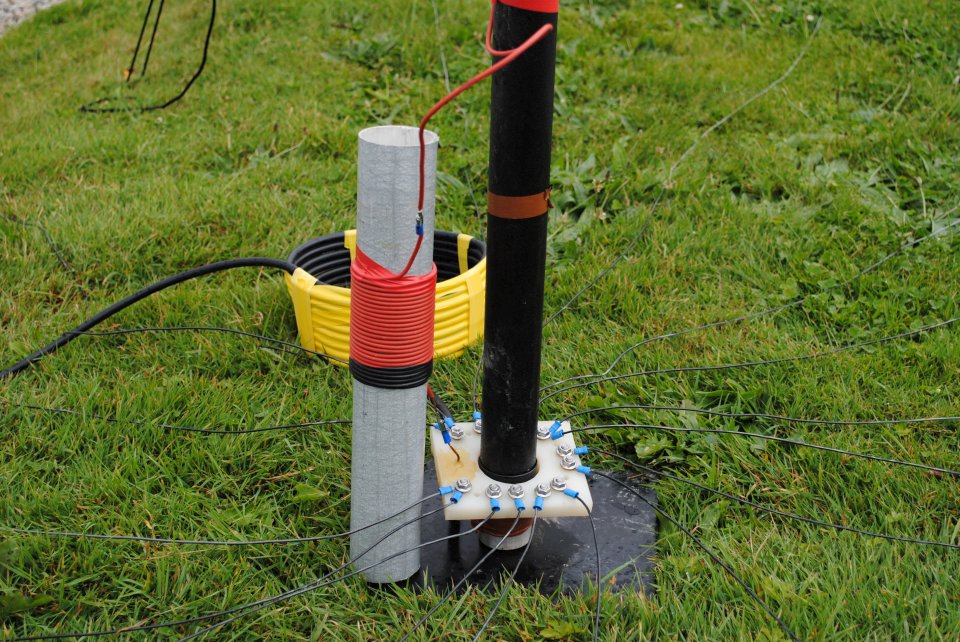
A picture speaks a thousand words, so, without further waffling, here is the prototype in action. It uses a regular DX Commander fibreglass pole which is around 9.7m in length with stainless hose-clamps using 8mm ID aquarium tubing (softened in hot water to push over the clamps). These clamps don’t scratch the tubing and securely hold each section from slipping down in a gale.

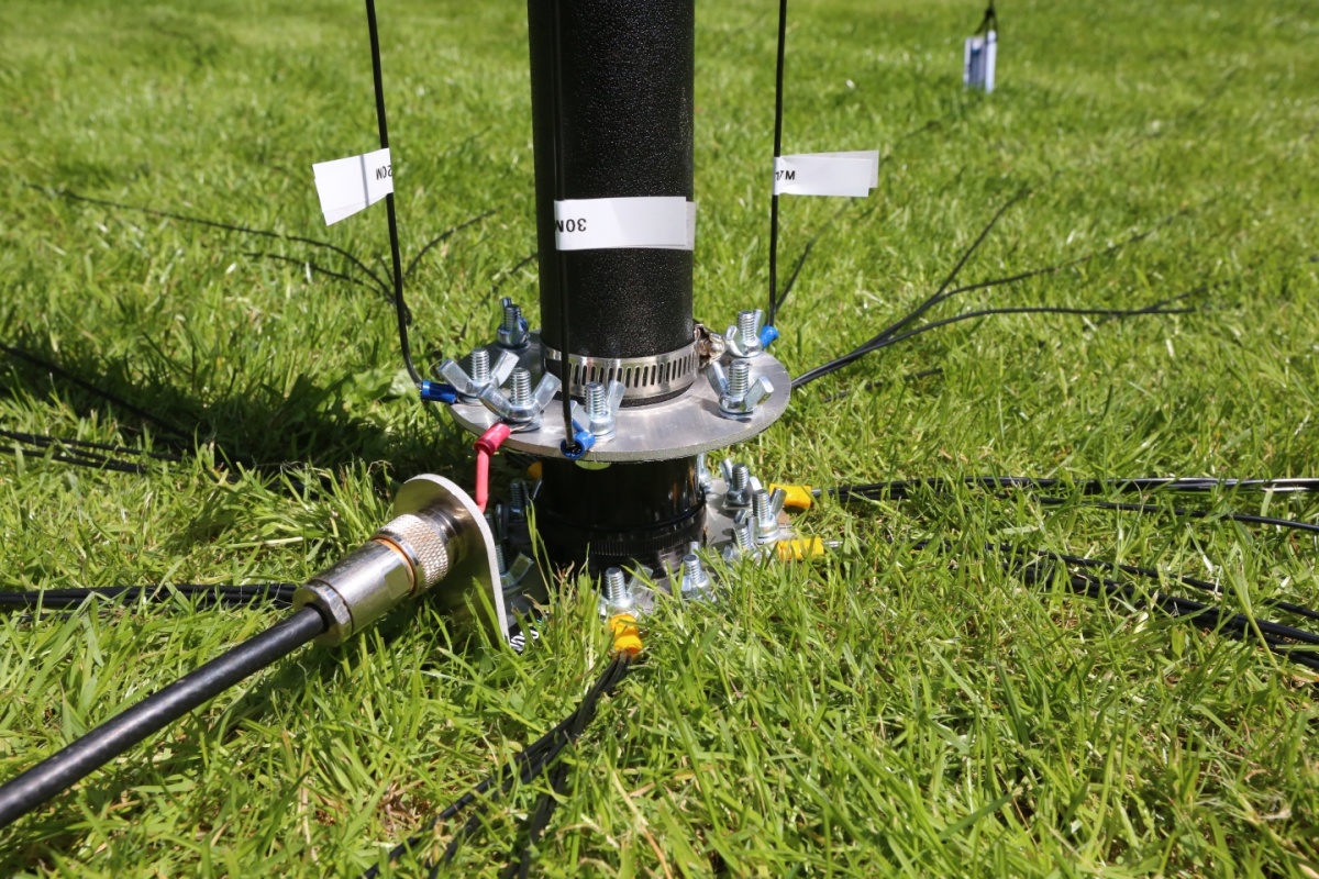
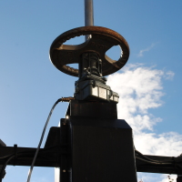
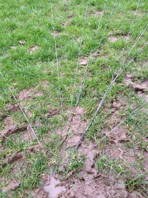
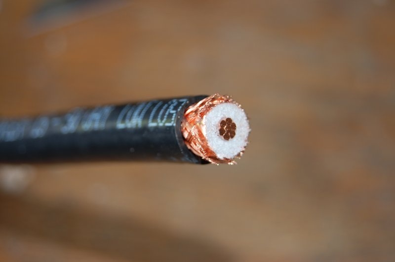
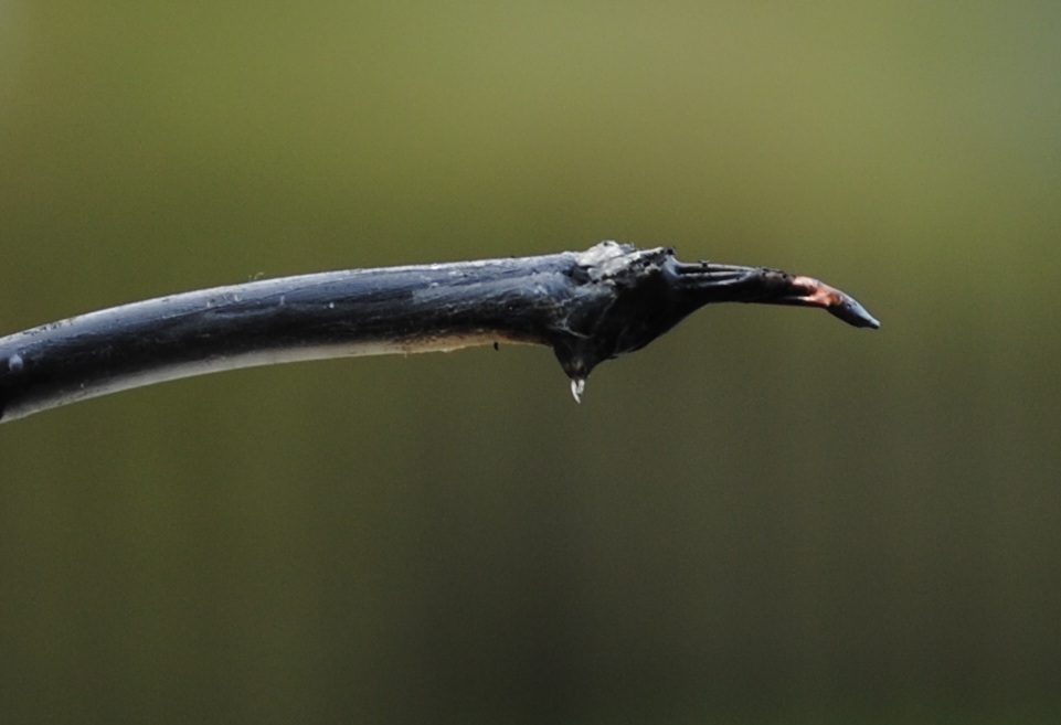
The base plate (radial plate) in the prototype is an aluminium angle with an SO239 fitted. The centre conductor is soldered with added heat-shrink and flooded with hot-glue. Connectors are used to connect to what I’m calling the “driven” plate with stainless nuts. RF enters the driven plate and self-selects the band it wants, just as a fan-dipole would. A guying point made from Nylon 66 keeps the elements optimally spaced as well as securely hold the mast upright at 1.2m off the ground to three guy stakes.

At the 5m point, a “spreader” plate houses the 20m and 17m elements on 3mm bungee cord with the 30m and 40m elements passing straight through. At the time I took the pictures, I had dispensed with the 15m and 12m elements.

In operation, I achieved better than 1:1.5 SWR across the operational bands selected. It was fun leaving WSPR mode running and allowing it to change bands without any ATU etc.

This antenna will comfortably handle 5000 Watts, although of course, the author only ran 400W RTTY for long periods for practical testing.

Hand-production of this system is extremely time-consuming so I am about to launch this with slightly lighter-weight and machined components to reduce cost. Target consumer price will be around £99. You’ll just need to add the wire and follow the instructions.

If you’d like to stay informed about progress, let me know.

Compact half-square for 40m band

I’ve just had an interesting discussion on 40m this evening with Peter, OH6GHI, also an antenna enthusiast. I happened to mention that I was listening to him on both VFOs. VFO A on my dipole and VFO B on my vertical and I found the stereo image very interesting as the polarisation of his signal to me changed.

half-square-basic-designWe got talking about half-squares and I confirmed that we were talking about the same thing, basically 2 x 10m verticals separated by a 20m top section. The half square is fed in one corner and according to my MMANA model, this should present 50 ohms and a great SWR curve across the whole of 40m.

Continue reading

Bidirectional switchable 40m wire yagi

I switched on the other evening and heard a very quiet DX caller on 7.142. It was YC0LOU from Indonesia and I could only pick up parts of his call. He called and called and had no takers. In fairness, he was extremely quiet but as the sun was gradually moving around the sky, he finally became audible and it was worth giving him a shout. 400w off my inverted V at 7m height got his attention but I needed a few blasts for him to get my call right. I put him on the cluster and he had a pile up.

Now, the point is, had I had more gain, I’d have not only heard him better, but he’d have heard me quicker too.

So I could add more height to my Inverted V but the difference between 7m and 10m isn’t actually that much at 5 degrees off the horizon – not even a db. Hardly worth writing home about.

40m-wire-yagi-drawingAnyway, this was the QSO that made me sit up and take stock of what I could do. I was seriously considering phased verticals for DX when I thought up the idea of having a switchable wire yagi. Either firing East or firing West.

Like me, you may already have an inverted V dipole up for 40m, all you need to is build another one about a quarterwave in front – or behind your existing dipole but out of a single wire. You don’t need to feed this with coax, it’s a parasitic element, like a 2 element yagi.

Continue reading

How to use dual coax feeders as ladder line

palstar-at4kHaving recently taken delivery of a Palstar AT4K manual tuner, I was keen to get her into production to replace my CG5000 in the attic.

Problem: the route to the attic from the shack is complex but I have a number of spare coax runs going that way including a couple of RG58 cables that I installed about 10 years ago as backups. Actually I originally installed three RG58 lines but I’ve been using one of them to send 12V up the line to the ATU.

parallel-cox-to-ladder-lineAfter MUCH research, I finally used about 20 feet of parallel coax feeders, connecting ladder line to both ends. To clarify, I run about 12 feet of ladder line from the ATU to the parallel RG58 cables. I soldered the ladder line to the inner core of the RG58 coax and shorted the braid-to-braid. My 20 feet of RG58 runs to the attic, through walls, up ceilings etc and in reverse, I connected the ladder line to the RG58. Again, I shorted the braids of each line to each other with a solder blob. My ladder line then has another run to the feedpoint of a large 60m loop that runs through the attic and around the garden.

The results have been quite amazing. Comparing my 40m reference dipole to the the CG5000 (SG230 type) ATU feeding the 60m loop has always shown that the loop was about an S point lower than my reference dipole for most stations.

Continue reading

Working 15m band on a 40m vertical antenna

Note: This article discusses the merits of a 3/4 (three quarter wave) vertical -vs- a 1/4 (quarter wave) antenna.

You can build a 40m vertical quarter wave antenna and ground mount it with 16 x 4m radials and operate it at the third harmonic; 21MHz.

Actually, all my experimentation has shown that if you multiply the quarter wave resonance by 3.03, you’ll have the next available usable band. In this case, if you tune a 40m vertical to 7.00Mhz, you’ll have the whole of the 15m band to play with with a centre-point of 21.300Mhz. Oh, and you’ll still have the whole of 40m band under 1.3:1.

Now here’s the controversy:

Most people who read antenna publications or the ARRL handbook believe that if you actually make this antenna, you’re creating a cloud-burner on 15m.

Technically correct (sort of) – but for DX, wrong.

On the surface, the 10m long 40m vertical that’s used on 21.225MHz does indeed look like a cloud burner. Here it is. 15m band in green -vs- a pure quarter-wave in red).

quarter-vs-three-quarter-wavelength-vertical-antenna-plot

(click to expand quarter-wave in red, three-quarter wavelength in green)

Continue reading

How heavy is a Cushcraft A3S TriBander Yagi?

The A3S is 14Kg (That’s 30 pounds in US money 🙂 )

I was worried that the combined weight of a Create Rotator an aluminium pole *and* DSC_0106
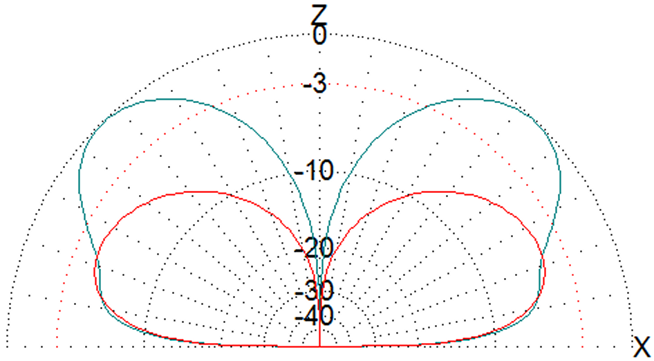
an A3S Cushcraft might be too much for my little lighting rig.

To test it out, I fitted the Create Rotator to the mast and added a 20Kg dumb-bell weight and started the motor.

It lifted without an issue so I’ll go ahead and plan to use the A3S for next field day.

How mad is that? !

How to build a tilt-over 60 foot antenna mast from scaffolding poles

This job is not for the feint-hearted. You will need a natural tendency for engineering, be accurate and be comfortable with knots. However, there’s no reason that most small teams of keen amateur radio operators can’t build this as a project for field day use.

Let me explain how I built the one shown in the pictures, then I’ll cover the learnings with you later along with my own do’s and don’ts.   Continue reading

How to fit T&K brackets to the corner of a wall

I love engineering challenges and I needed an elegant solution to mount a vertical antenna right on the corner of my house.
In the end, I used 3 x 24 inch T brackets from Barenco Antenna Hardware store. Poor Brian (Barenco owner) was a little confused by my request but he dispatched my order all the same and I’m pleased with the results.

By the way, a little tip. Don’t use those RawPlug type anchor bolts, they expand and they are tightened and could break off the side of the brick, particularly right on a corner. Instead, use Multi-Monti bolts. These cut a thread inside a pre-drilled hole. The beauty of Multi-Monti bolts is that you can remove them and re-install them at will. If you want to fill in the hole afterwards, use Frame Mastic from ScrewFix (or similar). You will never know your aerials were once there.

Continue reading

How to join antenna wire together

They used to call this the “AT&T Wiremans Join” but frankly, it’s the best way of joining wire together anyway. If you are joining insulated wire, first strip away about an inch of insulation of both ends.

If you have stranded wire, twist the strands on each wire together and solder them into a single fat strand.

DSC_0217

Continue reading

Raising Steel Antenna Mast on T&K brackets with pulley

I’m gradually swapping out any aluminium antenna poles for steel. Clearly these are very heavy, particularly with an antenna on top.

The trick is to use V bolts (like U clamps but in a V shape) and not to use saddle clamps because the pole will not slide easily past the U bolt saddle clamp.

Continue reading

What size pole to insert to a steel scaffold tube?

Most radio amateur operators look at a pole* and immediately wonder how they might use it in their hobby. It becomes a weird past time and can become somewhat of a burden when passing for instance, a section of tubing in a handy-man store. I have to stop and work out if they nest together – or will they go inside some other tube I might have.

However, I have solved one riddle which is what diameter pole can I slip inside a standard steel scaffold tube?

Continue reading

Solarcon Imax 2000 Review 5/8ths Vertical Antenna 10m

Dsc_0002
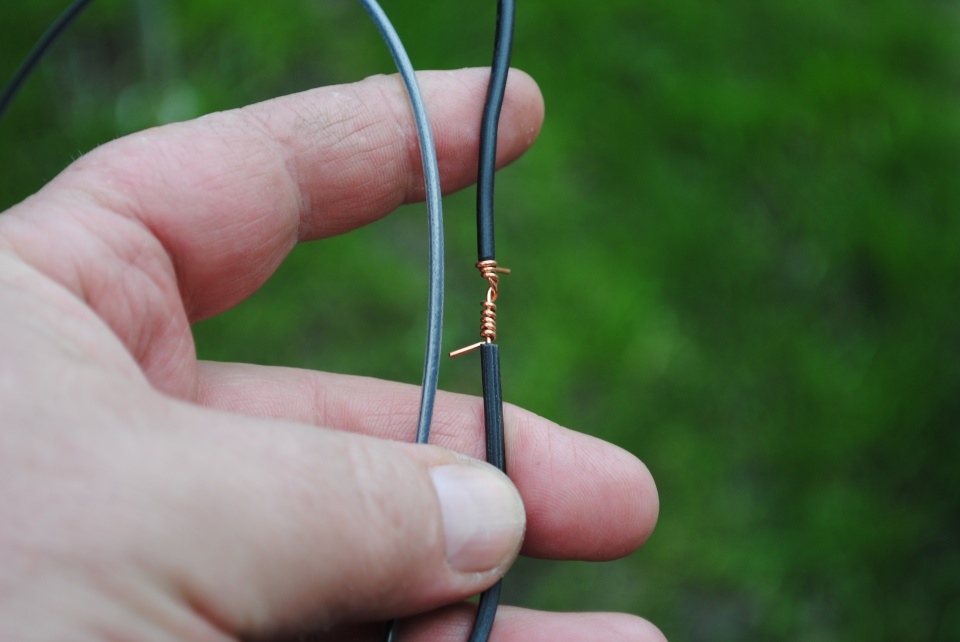
I always fancied a low-angle vertical for 10m band and after doing my research, came across the Solarcon Imax 2000. It was a toss up between this, a Sigma 4 copy or the Sirio 827. The Sigma 4 is now called the Sirio Vector 4000 and I discounted this one because of the size of the radials which seemed excessive for my plot , Same with the Sirio Vector 4000 which is just too tall. Even so, the Sirio Imax 2000 is still 24 feet in length. But read on, it’s actually fairly stealthy for such a tall antenna.

Continue reading

Aircell 7 coax review – vs- RG213

Dsc_0113I have used Aircell 7 now for a number of years and have finally replaced all my patch leads in the shack with precise lengths of Aircell 7 coax from SSB Electronics.

For longer runs, I’m still using Westflex and Ecoflex 15 but for portable operation, Aircell 7 is nice and bendy, easy to col up – and has pretty low loss, particularly for HF and short runs (up to 20m for VHF).

Continue reading

Salt spray detunes wires on fibreglass antenna poles

I use a lot of fibreglass poles with wires strewn up the sides, normally in a lazy helical fashion so that they don’t flap about too much.

I have great success with these poles as regular readers know however I have noticed that certainly wet weather can detune them ever so slightly. Effectively, they become slightly longer and I fathom that as the fibreglass supports become wet, I am achieving some slight inductance with the water that drips from the surface and gets between the wires and the poles. As soon as they are dry again, the tuning comes back to normal.  Continue reading

3 Element 40m Vertical Parasitic Array (VPA) Vertical Yagi

Essentially, this is a single 1/4 wave vertical antenna with ground radials, complimented by a pair of parasitic verticals; a reflector and a director. It will deliver around 6db of additional gain over a standard vertical with a beamwidth of around 70 degrees. I have built mine pointing 300 degrees so that I can work the US easily at night.

I call this the M0MCX VPA (Vertical Parasitic Array).


Hours of planning and modelling with MMANA has finally produced an excellent and extremely economical method of producing gain in one direction, although the front-to-back ratio isn’t superb, it still has some rejection.  Continue reading

Converting a 40m vertical to run on 80m / 75m band

Recently, I created a slightly loaded 40m vertical with 25 ground radials. It seems to work very well although the receive noise is pretty lousy compared to my loops and dipoles, however on transmit, it does seem to work as planned; a typical 1/4 wave pattern that outperforms regular dipoles at low angles of radiation.   Continue reading

Multi-banding 10m long 1/4 wave 40m vertical antenna for 15m band

I’m always curious to discover if a mono-band antenna will work efficiently (or otherwise) on another band. I recall that when I first studied antennas, it was explained that a dipole antenna will be resonant on every third harmonic. That means a dipole for 7.1 MHz should also work on the frequency three times bigger, in other words 21.3 Mhz. Actually, experience tells me that the real resonant frequency will be a little higher.

58 -vs- 14

1/4 wave vertical for 40m band can also be a 5/8th for 15m band

Continue reading

Using Petroleum Jelly for temporary antenna connectors

I’ve been trying to find a product to protect my temporary antenna connectors for either Field Days or my holidays near the sea. The problem is two-fold; firstly water ingress to the coax and the connectors from rain and secondly corrosion. The corrosion issue only seems to occur near salt water and spray and occurs within a couple of days.

petroleum-jellyI used to use self-amalgamating tape for Field Days but the effort in applying and removing it forced me to rethink. I started using high quality insulation tape instead – the stuff that has some nice stretch and doesn’t go brittle in the cold. This worked for many years. Unfortunately, the cheap stuff, from say Maplins might have the required insulation properties but has a brittle plastic feel and not very pliable – it’s certainly difficult to make waterproof between layers. Last time out for Wythall Radio Club SSB Field Day, torrential rain found its way through a crack between two layers of tape and the SWR went high.

Continue reading

How to make a stealth amateur radio wire antenna

Until recently, I had a) a 40m triangular loop in the back garden which I called a “micro-mega-loop” and b) a 60m loaded loop that allowed me to get on 80m. The two loops looked a bit horrendous not only because of the wire in the air, but because I used halyards to lift them in the air to the top of wooden stair rails. It was all very messy. They were also extremely close together along the back of the garden which meant some of my RF was absorbed by the other loop. See here: https://www.m0mcx.co.uk/sg-230-feeding-60m-skyloop-deltaloop/

DSC_0217I like loops for two reasons, a) for my small garden plot, I can achieve in half the size, what other do with a full size dipole and b) a resonant loop will also resonate on every harmonic, that means tuning a 40m loop at 7.1 Mhz means I also get 14.2, 12.3 and 28.4 Mhz.

Continue reading

Marine Vertical Installation with Radials

img_2150Having installed my old Shakespeare Marine vertical a while ago as a ground-mounted vertical, today was radial laying day. I’ve read that laying your radials out in the spring, across the lawn, means that the grass will grow up and gradually bury them under the grass thatch. I hope so!

Since I’m only having a test, I laid out 16 radials across a 180 degree arc. I can’t lay any radials in the other arc since the house is in the way.

img_2143I used PVC coated 7 strand D10 military wire which has seven small strands; four steel and three copper. They are the maximum length that fits in my small yard here, between about 6m and 12m in length. Near the feedpoint, I drilled a large hole in a piece of redundant 1 inch wood and fed all the radials through this and under some gravel to the ATU. I did the same at each end of every radial; a small hole which allowed the D10 to snake through before hammering them into the ground under tension.  Continue reading

Marine SSB Antenna Vertical or Horizontal

The diagrams included in this article were modelled with a program called MMANA. If you are inclined to give this a go, its a free download and I have produced training films on YouTube

NOTE: I have intentionally modelled the vertical antenna with a bad ground to replicate the findings of some fibreglass yacht owners who run a 15 to 20 foot copper ground strap to Dynaplates. I have modelled the horizontal antennas over sea-water.

This article follows my paper on raised feedpoint vertical SSB antennas for fibreglass boats. In this article, I look at an alternative; a horizontal dipole antenna which I will call an offset doublet and a Mk2 version, with a vertical component at the rear. We will continue to use the ATU matching device (often supplied by Icom) which will remove all the hassle of mono-banding and tuning. Marine SSB relies on a number of frequencies so an ATU to dial out the mismatch is vital.

Continue reading

Vertical Antennas for Marine SSB

This article discusses in layman’s terms how an antenna transmits its energy and the various factors that might affect its performance. The target audience is Foundation students and marine sailors since I discuss the positive impact of the sea as a ground, particularly those sailors with fibreglass boats who have vertical antennas mounted up high off the waterline. This debate started in the Yahoo Group, NordhavnDreamers.

Dipoles and Vertical Antennas

ecoflex-15

Coax showing centre-conductor and ground / braid surrounding

The energy from your transmitter is sent via its coaxial cable and connects to the “feedpoint” of your antenna which will radiate electromagnetic energy. Most modern transceivers expect to “see” a 50 ohm load at the point where the coax connects to the transmitter. It’s this reason why coax cable suited for transmissions is more often than not quoted as 50 ohm cable.

Antennas are a little bit like piano strings. If all the piano strings were set at the same tension, the longer strings would play a lower note and the shorter strings will play a higher note.

Continue reading

Budget Tilt-Over mast from Barenco

(This article contains an animation)

barenco-special-screenshot
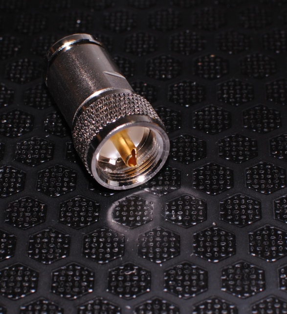
(Note, this product is at the “enquiry” level, it is not a stock part from Barenco)

If you haven’t heard of them, then you should. Barenco make the finest brackets and supply other amazing stuff for the amateur radio hobby. Here’s Brian’s link:

http://www.barenco.co.uk/

I dropped an email last month to Brian asking him for some custom work but explaining something in writing that will produce a piece of engineering can cause spurious results. I therefore used my new (free) toy, a 3D modelling program called SketchUp to show Brian what I was after.

Essentially, it’s an off-set, side-mount rotator bracket that is also tilt-over. Since the bottom of this mast will only be about 2.5 above the ground, I’ll easily be able to secure the rotator bearing, undo the bolts at the top and carefully lower the mast down with a 6:1 pulley set I have.

Here’s the walk-through as an animation:

6m Loop Fed Yagi Project

A few years ago, I bought a 6m yagi from Moonraker and James and I used it on one of our private field days. We found it difficult to get a great match but I thought I’d resurrect the project earlier this year to enter some random Saturday contest that was taking place on 6m.

Unfortunately, for love nor money, although I managed to assemble most of the bits, I couldn’t find the gamma match arrangement in all my Tesco boxes. I needed this because unfortunately the impedance of a three element yagi is well under 50 ohms so unless I went for just a two element beam, I would have to re-engineer things. I recall that a loop had a higher impedance, about 100 ohms. Using a closed loop system with a reflector and a director would bring the loop impedance down, probably by about half (according to the modelling) to achieve 50 ohms. I modelled it and things looked very promising. Wide bandwidth and pretty good gain.

Continue reading

Frying antenna wire with QRO

RF Weld - Click to zoom

RF Weld – Click to zoom

In the process of testing out my 80m coil this morning to load up my 40m vertical, I pushed 400w AM up the antenna and the ACOM went into alarm, telling me the SWR had gone too high.

Upon investigation, I noticed that just at the top of the coil, as the D10 comms wire kinked around some insulation tape and started its travels vertically, the wire had welded apart.

I made a repair using extra heavy gauge copper to take the high high current and all seems well again.

Continue reading

Adding a loading coil to a 40m Vertical for 80m operation

80m Loading CoilA successful morning today to convert my 40m vertical to an 80m vertical by adding a loading coil that I can switch out manually by just unplugging it. Nice and simple.

It’s not a great SWR curve due to the loading coil but I achieved 1.8:1 SWR at 3.79 Mhz, ideal for DX.

For the techies who want the dimensions: I wound 24 and a half turns on a fibreglass 2 and a quarter inch fibreglass former. The length of the coil itself is 3.5 inches.

Continue reading

Tuning a vertical antenna with the ocean tide

cornwall qthHere’s a new one that you wouldn’t read in the books.

I’m seriously hammering the 40m band here in Cornwall and have tuned the vertical antenna so that the whole of 40m SSB is almost 1:1 swr, certainly from 7.05 through to 7.1Mhz. Over the last few days though, I’ve noticed that the tuning might change over a few hours to give me some serious SWR headaches. Enough to force me at one point to fold back the top of the element by 70cms.

It took me a while to track down what was happening but it turns out that when the tide is in, the vertical is effectively closer to the salt water ground and requires to be shorter than when the tide has been out for a while, long enough for the salt water to drain out the sand and reduce the salt water table by probably 15 to 20 feet or so.

Continue reading

40m Quarter Wave Vertical, Cornwall

40m vertical

Quarter Wave Vertical 9.6m in length

I’ve tried many verticals and never had good results APART from this one.

This is a 9.6m long fishing pole and the length of radiator is the same. I fixed 16 x 10m long radials to an insulator that I had lying around. I would have preferred this to have been aluminium but I already had three of these. Most of these bits were salvaged from the three-element vertical array with raised verticals that James and I made back in 2009. Each bolt was bonded together with some copper wire that is out of shot, underneath the insulator and the radials were politely scattered in an approximate radial system on the ground. SWR is 1.0:1 according to my electronic controller on the Acom 2000.

The results have been amazing but I do realise that I had two things on my side; location by the sea and almost no electrical noise. Bliss.

As I write this, I’ve worked 48 DX entities over about 7 hours operating time on 40m. Quite incredible. I’m a convert.

Nested Quarter Wave Vertical Antenna 20m and 10m

20m 10m verticalWith my recent success at building fan dipoles that are more “nested” than “fan”, I saw no reason why I couldn’t put up more than one element on my 20m band vertical to achieve a match on 10m. I ran up a 2.4m length of D10 comms wire up the side of the pole, around 2 inches away from the 20m quarter wave element. After trimming a few centimeters here and there, it tuned it at 1.3:1 SWR and all was well.

To make sure everything really was good, I applied a QRO carrier and watched in amazement as the SWR hovered for a few seconds before moving up and down and finally going off the scale with the Acom shutting down with an alarm (what a great amp that is!).

It took a while to track this down but it turns out the D10 military comms wire had melted at the guying point about half way up the 10m vertical element. I had tensioned it around one of the bolts on the steel three-way guy point to stop it flapping around and it decided to try melt the insulation and finally and weld itself onto it before blowing itself apart. The joys of QRO.

The drivel written about antennas

Typical NVIS Far Field Plot
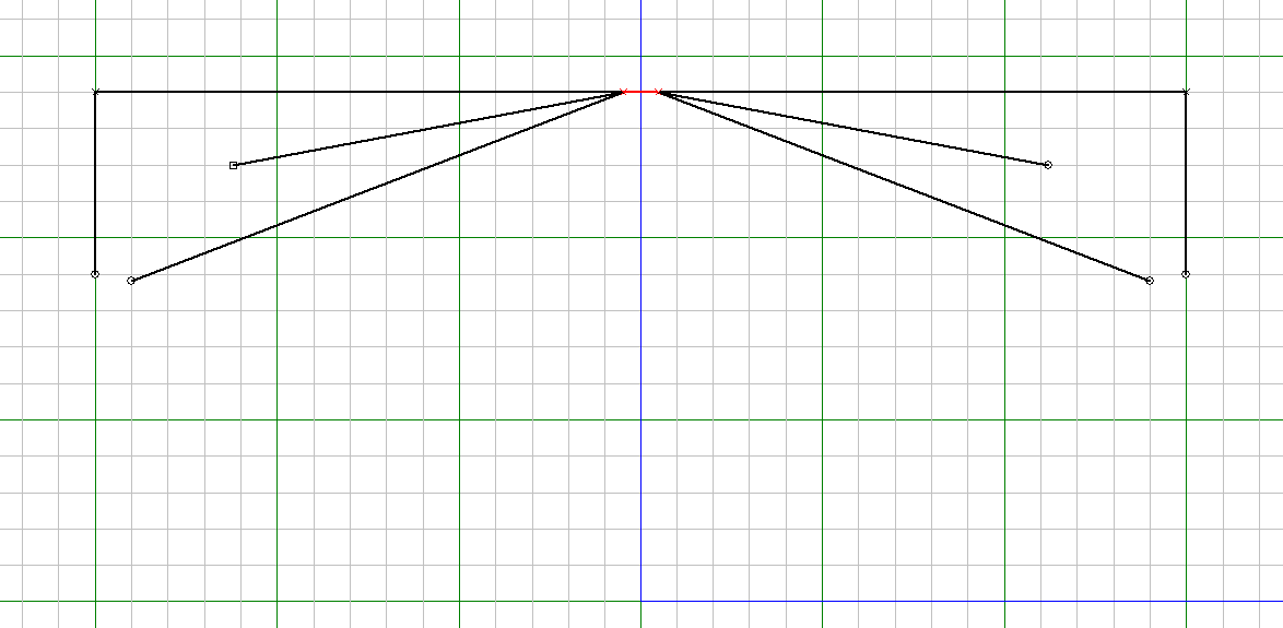
I check into the HamAntennas Yahoo Group fairly often and it occurs to me that collectively, there seems to be a lot of smoke and mirrors surrounding the design of low-band antennas and everyone seems to forget the basic principles, that low-to-the-ground antennas will form bubbles of RF above you. We call them NVIS or Cloud Burner antennas. The graphic is a plot of my home-brew 40m loop in the garden from MMANA. It’s 25 feet above the ground (which is exactly the same far-field plot as an 80m loop at 50 feet). Clearly it’s going to work well at what it’s designed for. Up to about 1,500 miles. In practice, it conforms precisely to my software plot.

Continue reading