This article discusses in layman’s terms how an antenna transmits its energy and the various factors that might affect its performance. The target audience is Foundation students and marine sailors since I discuss the positive impact of the sea as a ground, particularly those sailors with fibreglass boats who have vertical antennas mounted up high off the waterline. This debate started in the Yahoo Group, NordhavnDreamers.
Dipoles and Vertical Antennas
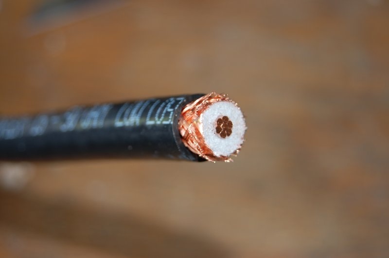
Coax showing centre-conductor and ground / braid surrounding
The energy from your transmitter is sent via its coaxial cable and connects to the “feedpoint” of your antenna which will radiate electromagnetic energy. Most modern transceivers expect to “see” a 50 ohm load at the point where the coax connects to the transmitter. It’s this reason why coax cable suited for transmissions is more often than not quoted as 50 ohm cable.
Antennas are a little bit like piano strings. If all the piano strings were set at the same tension, the longer strings would play a lower note and the shorter strings will play a higher note.
One of the simplest antennas is the dipole. The centre conductor of the coax connects to one half of the dipole and the ground (the braid) connects to the other side of the dipole allowing it to radiate. Dipoles are more often than not, mounted horizontally. They can be made from metal tubing but for longer frequencies in the short-wave bands, they are normally made from conductive wire.
This is actually three separate dipoles connected to one feepoint
It so happens that a dipole of the correct length for the frequency in question, presents itself as approximately 50 ohm load (for the technicians out there, this is normally quoted as 72 ohms however it depends on height above ground level) and therefore a “match” occurs between all the components, allowing all the energy from the transceiver to be radiated via the coax cable and away from the antenna.
Coax cable though can be lossy. In the main, thicker coax cable (say RG213) is less lossy than thin cable (RG58).
How big is a dipole?
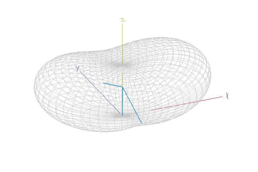
Typical 3D radiation pattern of dipole at half a wavelength above ground
Since I’m aiming this article at the the non-technical radio buff I’ll keep this simple but there is a tiny little bit of math involved to assist us that involves the speed of light.
Let’s pick a frequency on the marine band, say 8297 kilohertz (kHz) That frequency can also be quoted as 8.297 megahertz (MHz). If we do some basic math and divide the speed of light (meters per second) by the frequency, we get the wavelength.
We can round all these numbers down so that the calculation becomes:
- 300 / 8.297 = 36.15 (meters)
That’s 300 (speed of light) divided by 8297 kHz (frequency). So the wavelength at 8.297 MHz is about 36 meters.
Now, a perfect dipole will be exactly half of the wavelength; that would be 18 metres long in total. That means that each “leg” of the dipole will be 9 meters long (actually, it won’t be perfectly half the wavelength since there’s techno-boring stuff called velocity factors and height above ground involved but for this education, half will be just fine).
Verticals
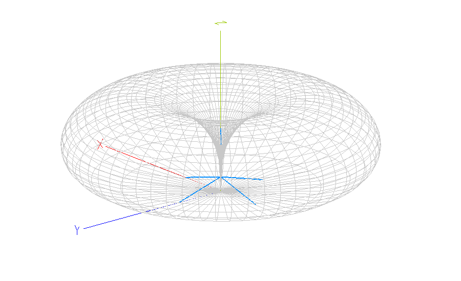
Typical radiation pattern of a vertical antenna. Can be drastically reduced due to ground inefficiencies.
OK, let’s transpose our learning into a vertical antenna. Dipoles can be mounted horizontal or vertical. Let’s take our horizontal antenna and make it vertical so that one leg would go 9m up the air and the other leg would go 9m down, all in free space with the coax feeding the centre. A huge antenna and not very practical.
The good news is that for vertical antennas, we can (almost) dispense with the bottom leg. Instead of feeding the antenna in the middle, we can lower the antenna onto the ground near the feepoint by connecting the earth (braid of the coax) to the ground (or the sea, for instance) and the centre conductor to the vertical bit of the antenna that goes straight up.
Unfortunately, it won’t work very well because there are losses involved unless we thoroughly connect the braid of the coax to the real ground. Amateur Radio operators have done much experimentation over the years and it transpires that if we place 120 wires on the ground, of approximately a quarter wavelength, all connected to the braid of the coax in a radial pattern, the antenna will become pretty efficient. By the way, that’s a lot of wire! In our example, that’s 120 multiplied by 9m, approximately 1,000 metres!
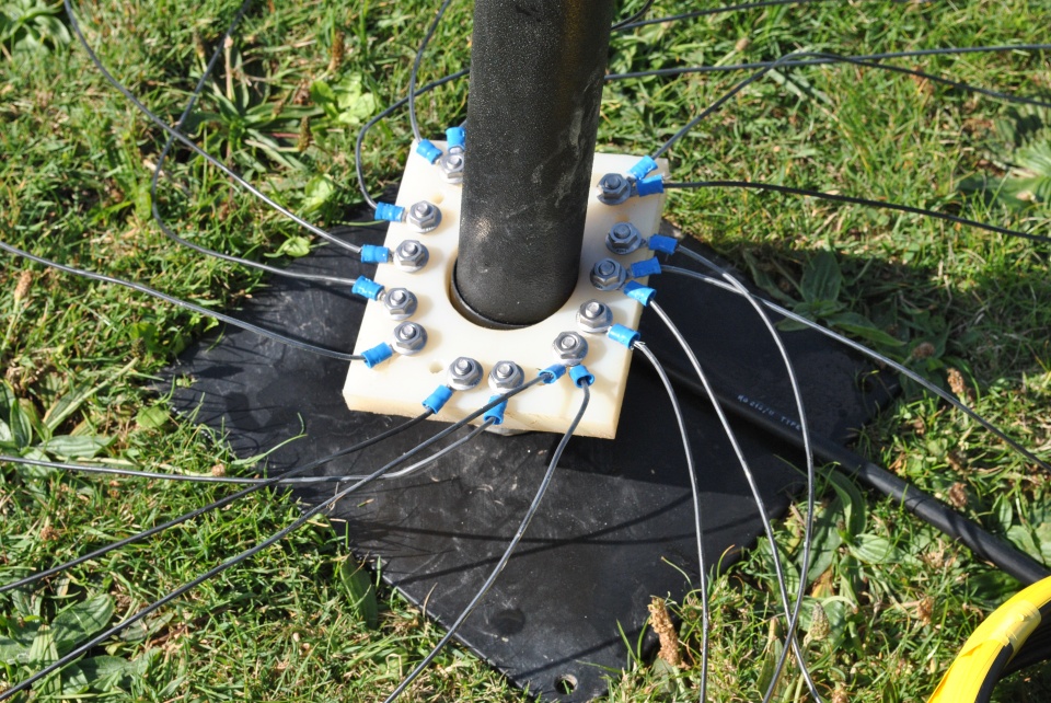
Example of a low number of radials that can be inefficient. 120 is the optimum.
How do we fit 120 radials to our boat? A quirk of nature means that sea-water happens to favour our antennas. It’s all to do with the salt. Basically, the sea starts to look like a lovely big expanse of copper sheet, but only if we can connect our earth efficiently to it. Any degradation of our earth will affect our signal due to the losses.
Ignoring the conductive qualities of metal boats, let’s deal with fibreglass ones first. Sailors have come up with a number of (mostly inefficient) engineering solutions to ensure they are connected to the sea as best they can. One method is to use a product called Dynaplate. This is a fancy metal plate which is partly porous and apparently makes extremely good contact with the water. Beware, this is still a very small contact area.
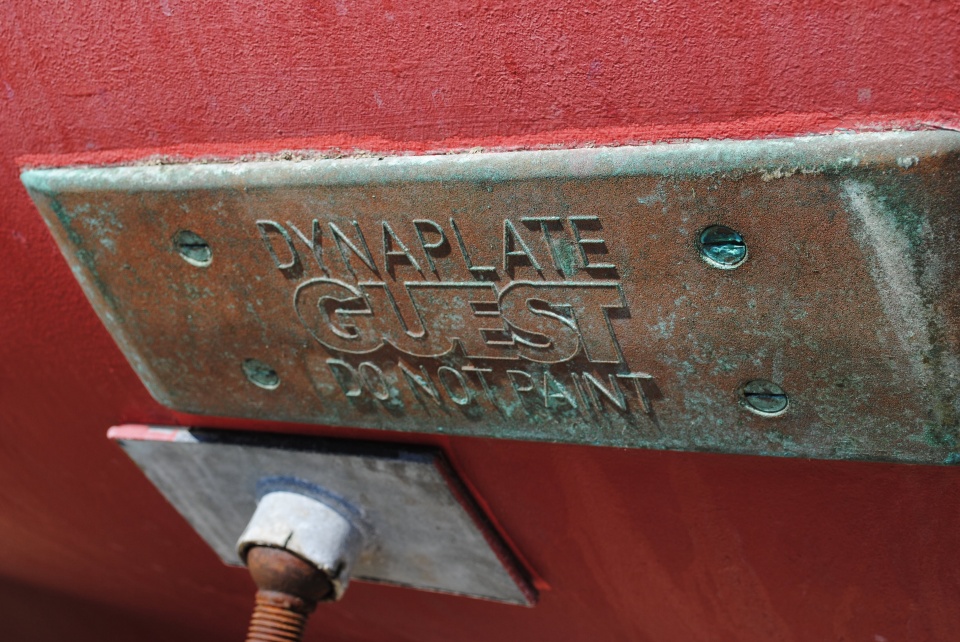
Dynaplate example fitted to a Nordhavn 46
OK, we have our transceiver connected to our vertical antenna with a length of coax. And assuming we had an approximately 9m vertical, we would be able to communicate only effectively on 8.297 MHz and that’s all. If we tried to change frequency, the match between the radio and the vertical antenna would change and the radio would gradually shut down and reduce power to compensate and protect itself from something called High-Standing Wave Ratio (SWR), which we aim to keep as low as possible. The best SWR meter reading will be quoted as an SWR of 1:1 (one to one). Since this article is aimed at people who are not radio geeks, I will not go into detail suffice to say that a 1:1 SWR assumes 100% of our signal is radiated (less other losses including ground).
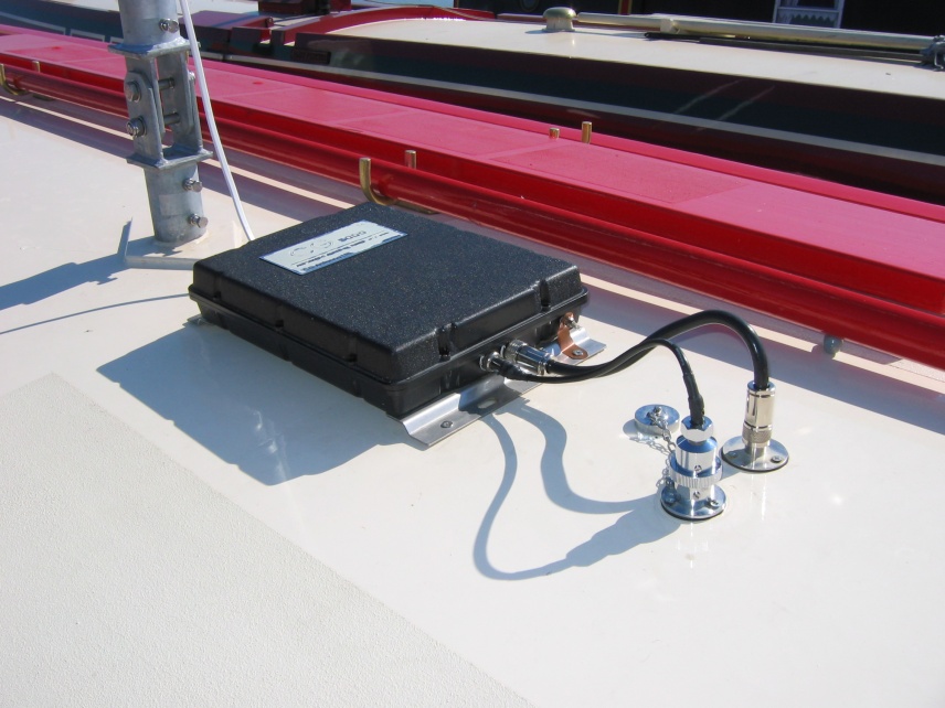
Similar to an ICOM ATU, this is an SG230 fitted near base of marine vertical.
To get around this problem of changing frequency, ICOM (and others) manufactured something called an ATU which stands for Automatic Tuning Unit. Basically, this connects at the feedpoint of the vertical and adjusts the match between your radio and the vertical so that it effectively always looks like a 50 ohm load, allowing most of the power to be transmitted into the antenna, tricking the radio into thinking it has a low SWR.
An ATU then, only matches the radio and the antenna. It has absolutely no bearing on the efficiency. Some people claim that because the SWR is low, the aerial is efficient. Wrong. You could match a lightbulb with an ATU, even a resistor with an ATU and have nothing radiated. In fact, amateur radio operators often use a large resistor called a “dummy-load” to transmit into nothing (and just make heat). Therefore, do not trust SWR. It has no relation to the efficiency of your antenna.
OK, we have our radio, an ATU, a vertical and a boat. As suggested earlier, on a metal boat, all our troubles are over. We don’t even need a Dynaplate. We connect the ground of the ATU directly to the steel deck with a copper grounding strip and it’ll work great. The paint on the steel (or aluminium) hull will be almost transparent to RF and we’ll have a wonderful ground plane to go and play radio with.
Marine Vertical fitted to steel boat
On a fibreglass boat, our troubles are just starting because a) The feedpoint from the base of the vertical to the ground can be variable depending on installation, from a few feet to many feet and b) Every device that generates low-grade rf interference, from fridges to inverters, will radiate small amounts of RF which go straight through the hull in every direction. This means the antenna will pick all that mush up, every click, pop and switch. On a metal boat, everything is effectively sealed in an expensive faraday cage and the vertical antenna will be clear of RF crud, in the clear at the top of the boat.
Sail Boaters
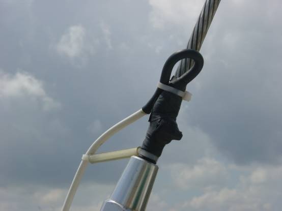
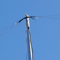
Back-Stay marine antenna installation example
(Photo inspiration click here).
Sail boaters have created a number of engineering solution and one is to use the back stay as part of the antenna, with the ATU mounted pretty close to the waterline, often near the stern of the boat, below decks. His earth can be good, using a combination of Dynaplates and leafing large amounts of copper sheet inside the hull. The relatively thin skin of the sail-boater’s yacht means that the copper can act well as a ground plane, as would a mobile SSB operator in his vehicle, effectively grounding his earth to the metal of the car or truck. The sailboater has an additional advantage over the vehicle operator though in that there is salt water all around to help his efficiency.
Motor Boats (eg Nordhavn)
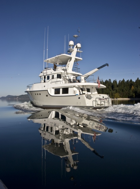
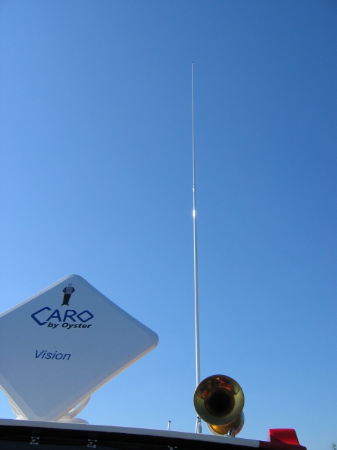
n55 Serendipity showing of her vertical antennas
Let’s deal firstly with the siting of the antenna. It is current practice to house all the antennas high, adjacent to the pilot-house. This is ideal for VHF antennas that don’t need a ground. VHF antennas can be designed another way on a fixed frequency and therefore don’t have an ATU. Being up high means they can see as far as the eye and frankly, the higher they are, the longer the range. Further, VHF antennas in terms of wavelength are extremely high off the waterline and because of this, the pattern of RF that is radiated is extremely flat, like a horizontal, flattened donut – radiating in all directions at once.
Ground mounted vertical antennas have a tendency to radiate their signals in a fatter, taller donut because they are closer to the earth than a VHF aerial. Thats OK, we don’t often need our take-off angle to be too low for SSB. Typically, we need 1,000 to 3,000 mile transmissions and for this to be successful, the ideal take off angle for our RF energy is somewhere between 20 and 45 degrees from the horizontal.
But we have a conundrum. From an RF engineering perspective, the SSB antenna needs to mounted as close to the water as possible so that we can take advantage of the earth. But if we made this a reality, say somewhere near the stern by the cockpit, the siting would probably foul any good mooring practices with deck hands having obstacles to surmount when dealing with lines and fenders. From an RF engineering perspective, this would be the best. I imagine a solution to the earth issue would be by lining the lazarette with a copper mesh, and additionally bolting say 4 equally spaced very large Dynaplates under the hull each side of the prop shaft and maybe more copper mesh running though the hull all the way forward at the point of manufacture. Mounting the ATU at the base of the vertical somewhere near this point would at least make the antenna pretty efficient.
Why not up high then?
Nordhavn Yachts make a fabulous, world-class boat but I’m wondering if SSB will ever work on these boats with a vertical antenna, simply because the feedpoint to the HF (SSB) vertical is high(ish) off the waterline and there is only a single copper strip connecting to one Dynaplate. You will recall the 120 radial engineering solution earlier on? Well, we’re down to one here, and not even 9m long. No, at best it’s maybe 4m long, it basically goes straight down and it connects to just one grounding plate. Worse than that though, the ground foil that connects to the Dynaplate terminates somewhere near the pilothouse where the ATU will be fitted. But let’s say the ATU is fitted a metre away? The installer will wire up the 12V, connect to the copper foil with a piece of wire (a metre away) and then run the antenna out of the ATU, past some wiring (who know what next to) and route to the base of the antenna.
Where does the antenna start? Immediately at the ATU. Therefore, the ATU, the base of the vertical *and* the copper grounding foil / strip all need to be sited within a few inches of each other.
Seriously, if I was building a Nordhavn Yacht and was contemplating SSB, I would either:
a) Fit a stern-mounted antenna (as per sail-boats) and line the hull with copper mesh during construction. However, I would be worried about mooring issues with my deck-hands, as discussed.
b) Dispense with the vertical and instead mount a random, horizontal dipole with the ATU and feedpoint above the pilothouse. The front half of the dipole would be mounted between the ATU and a forward mast at the bow. Not sure of how the stern facing emlement would be mounted and consideration would have to be made regarding davit usage. Dipoles don’t rely on a ground, they are a balanced antenna with both halves working together. You can have an off-set dipole, that would work fine. For instance, a total of 50 feet of off-set dipole could be constructed with a single leg of 35 feet towards the front and another leg of maybe only 15 feet going backwards. Radio Amateurs might call this an off-set Doublet.
c) Come up with a sort of an elevated radial solution. Dispense with the Dynaplate totally and gauze the whole of the superstructure from the pilot-house and upwards over the top of the flybridge in copper mesh at the time the fibreglass was being laid down and place a wide copper grounding lug for the ATU to connect to. There are other considerations with this option, too many to list in this article but that would also work pretty effectively.
Points to remember:
- The ground is the most important part of an HF vertical antenna system
- SWR has no relation to antenna efficiency
- Interference from internal electrical systems may be more of an issue on a fibreglass boat than a metal boat
Post Script: I’ve just remembered that Nordhavn often supply literally tons of lead ballast on their trawler yachts. You could connect all this together and bond with copper tape / foil or strip.
Further reading:
There are many articles on the internet about radials and earthing to the sea and randomly I enjoyed this one by Rudy Severns N6LF. I also enjoyed the article by Kenny Silverman, K2KW and Tom Schiller, N6BT and in particular, their “Lesson #2”, about half-way down the page. Sailors beware.
This is another great from James Baldwin. His advice seems to mirror mine. An Inverted V dipole would be a great temporary test of your equipment and if I ever get my hands on a Nordhavn for a day or so, a temporary Inverted-V dipole is precisely what I’f fit with a few cable ties as a test.
My thanks to my panel of experts; James Thresher (M0YOM), Chris Pettit (G0EYO) and Dave Pick (G3YXM) for their input.
The photo gallery accompanying this article follows:

