 [EDIT] This is a very old post from about 2018..
The shop is on the link to the right, else the VERY OLD article is below:
I finally found some time this year to pull all the components together to test out in a real-world setting, the idea of using multiple elements on a single vertical fibreglass pole to achieve very good SWR and radiation patterns.
The problem with verticals is than in the main, people need either ATUs or they use that awful UNUN business with a single radial. The 9:1 UNUN business is just inefficient and the only way to to use an ATU effectively is at the feedpoint, not at the rig-end due to the severe losses.
A feedpoint ATU is expensive and generally requires a 12V power source. And long verticals have awful radiation patterns beyond 5/8th of a wavelength.
So the only way to reliably install a vertical and dispense with any worries about SWR and power handling is to build a mono-bander.


")


Regulars will know that I’ve been playing with the idea of adding separate elements to a 40m vertical mono-bander to add in the odd frequency, say 20m – but the interaction between elements can cause impedance issues (read SWR).
With development, I’ve discovered the optimum spacing between elements to achieve pure quarter-waves on 40m, 30m, 20m, 17m and 12m. It happens that the 40m vertical will resonate on 15m for excellent very-low radiation patterns and with the addition of a shorter-then-normal 10m element (around 2.6m in length) one can get radiation with a regular quarter-wave pattern, although the idea of using a ground-mounted vertical for 10m is slightly off-putting. There are other methods to get good radiation on the 10m band.
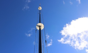
A picture speaks a thousand words, so, without further waffling, here is the prototype in action. It uses a regular DX Commander fibreglass pole which is around 9.7m in length with stainless hose-clamps using 8mm ID aquarium tubing (softened in hot water to push over the clamps). These clamps don’t scratch the tubing and securely hold each section from slipping down in a gale.
The base plate (radial plate) in the prototype is an aluminium angle with an SO239 fitted. The centre conductor is soldered with added heat-shrink and flooded with hot-glue. Connectors are used to connect to what I’m calling the “driven” plate with stainless nuts. RF enters the driven plate and self-selects the band it wants, just as a fan-dipole would. A guying point made from Nylon 66 keeps the elements optimally spaced as well as securely hold the mast upright at 1.2m off the ground to three guy stakes.
At the 5m point, a “spreader” plate houses the 20m and 17m elements on 3mm bungee cord with the 30m and 40m elements passing straight through. At the time I took the pictures, I had dispensed with the 15m and 12m elements.
In operation, I achieved better than 1:1.5 SWR across the operational bands selected. It was fun leaving WSPR mode running and allowing it to change bands without any ATU etc.
This antenna will comfortably handle 5000 Watts, although of course, the author only ran 400W RTTY for long periods for practical testing.
Hand-production of this system is extremely time-consuming so I am about to launch this with slightly lighter-weight and machined components to reduce cost. Target consumer price will be around £99. You’ll just need to add the wire and follow the instructions.
If you’d like to stay informed about progress, let me know.