The diagrams included in this article were modelled with a program called MMANA. If you are inclined to give this a go, its a free download and I have produced training films on YouTube.
NOTE: I have intentionally modelled the vertical antenna with a bad ground to replicate the findings of some fibreglass yacht owners who run a 15 to 20 foot copper ground strap to Dynaplates. I have modelled the horizontal antennas over sea-water.
This article follows my paper on raised feedpoint vertical SSB antennas for fibreglass boats. In this article, I look at an alternative; a horizontal dipole antenna which I will call an offset doublet and a Mk2 version, with a vertical component at the rear. We will continue to use the ATU matching device (often supplied by Icom) which will remove all the hassle of mono-banding and tuning. Marine SSB relies on a number of frequencies so an ATU to dial out the mismatch is vital.
My findings show that a badly installed Vertical antenna is seriously outperformed by a Horizontal antenna. Further advantages are also discussed.
Radiation Patterns
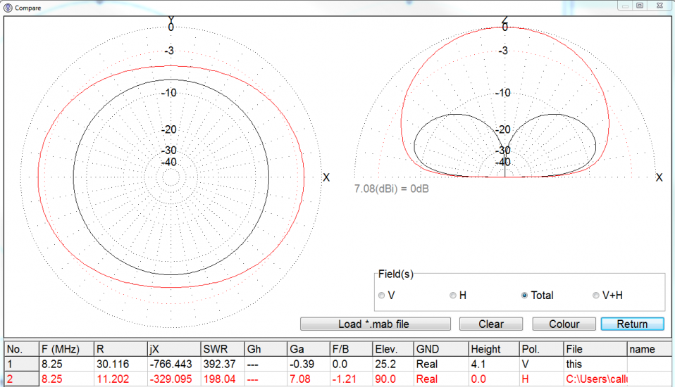
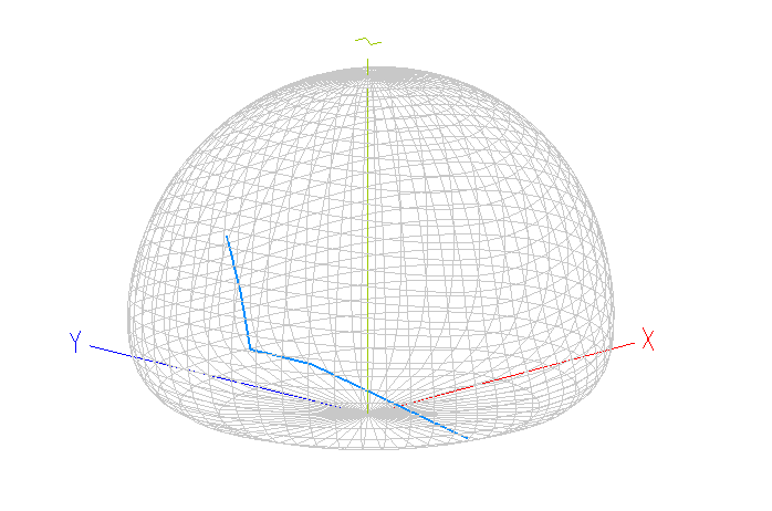
Badly grounded Vertical (black) -vs- Exceptional over-sea doublet dipole (red)
Vertical antennas have a radiation pattern that looks like a donut. This means that most of the radiation is pushed out towards all sides. On VHF, having a high mounted, very-high gain VHF antenna means you can speak to boats further away and contact land from many miles out to sea. VHF radiation patterns are very flat.
For HF, the pattern of a vertical antenna is much less squashed flat. It’s really quite fat and chubby for a number of reasons including the gain of the antenna itself and the height above ground relative to its wavelength. If you compare marine VHF at approximately 2 metres in wavelength to a signal at 8.25 MHz (which is 36 metres long), it’s pretty clear that it’s almost impossible to achieve just one wavelength of height at 8 Mhz, even on a large mega-yacht. VHF antennas on the other hand are more-or-less in free space, many wavelengths above the ground (sea). VHF antennas also have a couple of tricks up their sleeve as well which means they can have greater gain, causing an even flatter donut. They don’t create more energy, they just squash the radiation pattern out flatter so it goes further. You can imaging this by inflating a balloon and squashing it flat with a dinner plate. The same amount of air (energy) in the balloon; it reaches further to the edge of the dinner plate.
A fairly low-to-the-ground horizontal dipole though, say less than a quarter of a wavelength off the ground (or the sea), has a big bubble of RF radiating all around it. If we only had these two antennas available to us, the vertical antenna should be preferred for very long distances, from 1,500 miles and more. For less than 1,500 miles, a horizontal dipole might outperform the vertical. This assumes that the vertical antenna is super-efficient. Unfortunately, the vertical antenna is one of the most difficult to get right, particularly on non-conductive boats with high feedpoints – due to ground losses, as my previous article eluded to.
Whilst we’re on this subject, bear in mind that in the main, antennas receive using the same lobes of radiation patterns as the transmit signal, so if your aerial transmits well, it will receive well too and visa versus.
How does the signal reach our destination? (Propagation)
In my previous article, we chose a frequency in the shortwave band at just above 8 MHz in one of the marine bands. Let’s stick with this and see exactly where our signals go.

In the main, our shortwave signals need to bounce (to be precise, they refract) off the ionosphere. The lower of these ionosphere layers is quoted as normally being between 150km to 220km above our heads. A great little read on the ionosphere is found here.
Using some simple maths and assuming a take-off angle of 30 degrees, our low-frequency HF signals will achieve a distance of around 600 miles, assuming we’re using the F1 layer (8 Mhz and below during the day – mostly). The F2 layer is higher so signals will refract across a longer path, but that’s more suitable for the higher frequencies. Our 8 Mhz signal will pass straight through this normally meaning that’s useless until we reach 12 Mhz (or thereabouts). At the higher frequencies, the F2 layer refracts, causing longer distance communication.
So, in the main, the lower marine frequencies favour the F1 layer (zero to 1,000 miles) and higher frequencies will favour the F2 layer (500 to 3,000 miles). There are some great articles on the internet regarding which frequency to use at which time of day, so I won’t procrastinate further, let’s get back to the aerials.
Vertical – vs- Horizontal
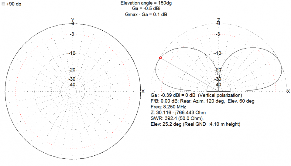
Intentionally degregaded Vertical Antenna showing approx 0 db gain at 30 degrees
I’m sticking with our target frequency of 8.25 MHz or thereabouts.
Vertical
A marine vertical antenna will favour its strongest lobe of RF at between 10 and 30 degrees off the horizon with a very strong attenuation decay starting to happen from 30 to 45 degrees and up. Frankly, it starts to become pretty unusable for reliable communications above these take-off angles. Basically, there is very little power being transmitted above the antenna.
Horizontal
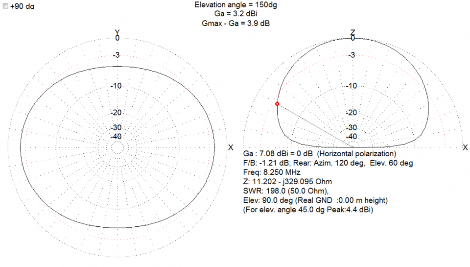
Over-Sea doublet / dipole with feedpoint 20 feet above sea level
A horizontal antenna, over the same ground plays catch-up with the vertical antenna at low angles at around 20 degrees off the horizon. Essentially losing the very low angle gain that a vertical antenna can display (if properly installed!). This means that it can compete in the 500 to 1,000 mile radius arena extremely effectively, normally more so. However, the advantage of a relatively low-to-the ground dipole is that the bubble of RF that radiates between 40 and 90 degrees, will allow communication in the zero to 500 mile range as well, something the vertical has a huge problem with. From personal experience, certainly zero to 200 miles is almost impossible with a vertical antenna in the 40m band (just below the marine 8 Mhz band with similar characteristics) just the opposite of the dipole.
Note the difference in gain figures (middle top in the diagrams). At 30 degrees, the horizontal dipole appears 3db better than the (intentionally degraded) vertical.
The further up the frequency range we go, the higher the antenna becomes as a percentage of its wavelength above ground. For a horizontal dipole therefore, this means that at say 16 Mhz, instead of having a bubble of RF straight above us as we had in the 8 Mhz band, the sides of the bubble start to stretch out as the horizontal dipole becomes higher off the ground (in percentage terms). This means that our long-distance frequencies (which is what the higher bands do for us) become more effective too. In the main, the radiation will start to squash out the sides of the dipole as the dipole effectively becomes higher (I will model this when I have time to show you).
Man-made interference; vertical -vs- horizontal antennas
Most RFI from man-made sources will inevitably be radiated to your antenna at a very low angle, ideal for your vertical antenna to pick up since that where its main gain is. Other boats, the marina, buildings, street lighting etc will radiate general RF crud. It’s all throwing stray RF everywhere and your low-angle vertical will pick this up wonderfully because it’s main RF energy lobe is effectively pointing at it.
Remembering that our transmit lobe is the same as our receive lobe, and noting that our horizontal dipole has a natural null from zero to around 10 degrees, less man-made interference will be picked up with our horizontal antenna – allowing your receiver to work more effectively.
If you couple this issue with a badly installed vertical, so that your receiver is working flat out, trying to make sense of any energy that it can find, it’s likely to enhance the interference even more, destroying the likelihood of a achieving a satisfactory receive signal from your chosen station.
So why use vertical antennas?
Actually, I don’t really know. It’s probably because aesthetically, they match our other VHF antennas on board and they don’t get in the way of people, davits and other equipment.
Of course, superbly installed verticals will work, if you really do want to talk to some random person or receive a weather fax from 1,500 + miles away, they will be great. I know – I have built a number. But they’re not magic; a horizontal dipole or other horizontal arrangement will work very effectively (with less smoke and mirrors!) particularly in the zero to 750 mile range. I come back to the fact that it can be a real pain to get a vertical working, particularly on a non-metallic boat with a raised feedpoint.
How to install a horizontal dipole on motor vessel?
Version 1:
Assuming you fancied junking the vertical and actually having the ability to use SSB on board, then this bit is for you.
On a metal (conductive) boat, achieving some height off the ground (sea) for your horizontal dipole / doublet (what ever you like to call it) is difficult. Your horizontal antenna will have a reflector extremely close to it (the deck). Weirdly, this is where non-metallic fibreglass or wooden yacht actually starts to win the fight for this stealthy antenna. Yes, there will be wiring and copper pipes and all sorts of metal nearby, however the actual hull is transparent to HF signals, so the height above ground of the horizontal antenna is just about the right height; say 20 to 30 feet.
 It so happens that most of the energy from your aerial will be transmitted near the feedpoint, so mounting this right at the top of the yacht and running a conductive transmission wire from a small stainless forward mast at the bow to the ATU should be fairly practical. Of course, you will need one or two ceramic insulators so that the hand rails don’t become part of the antenna system. Getting a wire towards the back of the boat from this feedpoint could be achieved a number of ways. My preferred option would be to use the top half of a 28 foot marine vertical (13 feet), screwed into stainless 1 1/4″ threaded receptacle at the back of the flybridge, pointing backwards. The stainless threaded housing would connect to the ATU perhaps inside the flybridge roof, away from the element.
A stainless turnbuckle will be required at the forward end to tension the stainless antenna element up to around 15 kilos (guessing) so the connector housing a ceramic insulator on the flybridge roof may have to be reinforced.
Version 2:
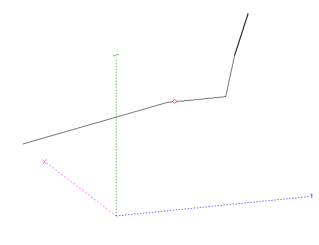
Mk2 Doublet with rear 13 foot Vertical
I played around with the model in MMANA and noticed that if the last 13 feet of antenna was installed vertically (my drawing shows a slight incline to the rear but I have also tried this vertically and the modelling suggest negligible difference) then similar results could be achieved. I noticed only a 0.2db fall-off in gain.
How to achieve this? Well, it’s even easier. Just ask your antenna manufacturer to supply a connection point where the mast joins together and connect it there (most of these are supplied in two or three sections that screw together).
You will have to ask them to sever the connection between the bottom mast and the top extension so that only the extension is doing any work and no RF is going “down” the mast as well (although I haven’t modelled this, it might actually be a benefit!).
So, instead of the wire antenna going completely to the back of the centre/middle, just diagonally move it off to the side of your flybridge and connect it to the top half of a large SSB antenna, perhaps route it through a shiney white fibreglass pole and noboy would know.
Of course, you will also require a tensioner up near the bow mast to add some load to stop the wire element flaying around.
And for those yachts that already have a forward mast (some Nordhavn 62’s have I believe), this installation is even easier.
Far-field plot of Mk2 marine doublet with rear 13 foot vertical showing only 0.2 db down on almost horizontal Mk1 doublet
I am particularly excited in that the antenna modelling is extremely encouraging in this Mk2 model with a combined vertical and horizontal radiation component that is only 0.2db down on the flat version – and aesthetically, very much more pleasing.
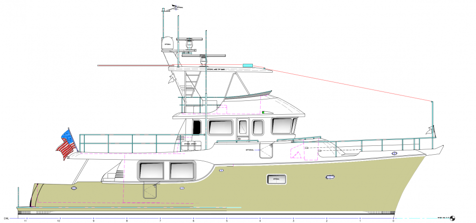
Using a Nordhavn 60 as my demo model: Mk2 Marine Antenna by M0MCX, horizontal component with 13 foot vertical rear section. Total length around 50 feet (15 metres)
For either of these versions, the ATU doesn’t have to be where the aerial actually connects to (the feedpoint). You can use something called ladder-line from the ATU to the feedpoint. Ladderline doesn’t radiate because each side of the ladder cancels the other out and is extremely low loss, even better than coax. This means, you could site the ATU in a convenient place inside a console somewhere and as long as the ladder-line was routed away from other metal and cabling by a foot or so (like through a ceiling, up a column and inside a roof void), you could have the feedpoint terminated by a pair of high-quality ceramic insulators at the top of a small hollow fibreglass mast. This will have the benefit of raising the feedpoint, where the main radiation is at its greatest. I’m sure the engineers amongst you would be able to work out a practical solution to this.
Conclusion
I have modelled all my antennas before building them and without fail, they have performed as expected. Sometimes I didn’t believe the numbers and have built “failed” antennas, only to remember that the model was right after all.
This system, particularly the Mk2 as I describe, would give you a very strong receive and transmit signal throughout the marine HF bands. I will need to check the minimum requirement of length of wire for the Icom. I have an SG230 (similar model aimed at the amateur market) and a CG5000 (800 watt version). The SG230 will easily load this up so assuming Icom have the loading and capacitance capabilities of the SG230, this antenna will load up and people will be amazed at how strong you are. I mention the CG5000 because Mydel supplied this with much less of a tuning range so I might have to “assist” with a small coil somewhere in one of the elements.
So, you can receive weather faxes with ease and talk to people up to 500 miles away very easily – and be heard, stretching to 1,000 miles in the morning and at dusk (just on 8 MHz).
I have to remember that Icom SSB transmitters “only” have 100 watts output which is quite a lot less than I use normally however just recently, I was restricted to 100 watts whilst on away-day and comfortable loafed all over Europe in a 650 mile circle of RF quite happily without any amplification. I could hear – and be heard by all stations.
Experiment
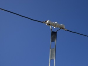
Example of ladder-line with a ceramic insulator. Picture found at http://www.rogerwendell.com/images/mystation/450_ohm_ladder_line_zepp_04-20-2008.jpg
Now we need an experimenter to install this (on a temporary basis) with any old piece of wire to a fabricated wooden mast at the bow and a wire draped of the back of the boat, tied down on a temporary basis. Disconnect the whole current antenna system from the vertical and the ground from the ATU then use ladder-line (again temporarily) to the feedpoint.
I think you’ll find it work like a charm.
PS – Here’s a picture of ladder line that you should be able to hide behind various panels as well as an example of a ceramic insulator. Frankly, this is just for fun, your install should be stainless and top-notch.