Well folks, I’ve been continuing my experiments with my two sky loops (closed loops of wire held above the ground at three or more points) and comparing them against various verticals. Sometimes the verticals win, other times the loops do. I’ve had 8m verticals and longer too. Today, I’ve put the 12m vertical back up (https://www.m0mcx.co.uk/?p=102) fed with my trusty SG230 coupler. I may add that anyone interested in fast antenna experiments should get one of these. A tremendous piece of kit. Matches anything.
 Apart from the noise factor (loops are quiet), the vertical seems to make a better impact on transmit more often than not for DX, unless I’m into NVIS or near NVIS (500 miles or so). Even then, up to 1,500 miles, the jury is out – either antenna can win. Beyond 1,500 miles the vertical seems to do a better job most of the time – not always, however my loops are very low to the ground, maximum height of 7 meters. On 40m, I would say the vertical is a better antenna to have almost all of the time unless you need NVIS for local copying – and with the sun spot cycle as it is, you won’t get this for a while yet!
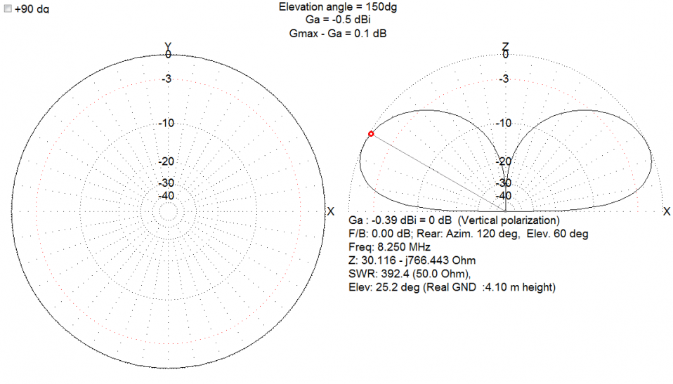
I used to have the opinion that loops were more often than not, cloud warmers. However let’s face it, so are almost all low-to-the-ground HF antennas. My interest was tickled recently when VE7HA mailed me an MMANA file of a very high (80- foot) 300 foot circumference skyloop that he had built with three very large trees. He claimed great contest results with this loop. I had a look at the plots. Yes, he was right.. Check this out, 10.4 dbi gain at 5 degrees to the horizon on 10m? On 15m band, we’re looking at 12.5 dbi at 7 degrees to horizon! On 20, it’s as good with 10.5 dbi gain at less than 10 degrees.
 Now.. This is a very different animal to the Skyloops that most people build. If you want a pile-up generator, this is the animal to have. It fundamentally, takes all your RF energy and pancakes it low to the ground in various star shapes. Very Of course, you will sometimes null out the station you want but you could get really clever and change feedpoints with relays. But ignoring the clever engineering, this has changed my mind as to the effectiveness of a high skyloop.
Be prepared to get into some matching territory though, ideally an automatic coupler at the fedpoint with open wire feeder, or perhaps an olde-fashioned tuner in the shack!
Some day I will build one, I just don’t have the trees 🙁
(Years later: I did build one. They’re amazing).
73
Callum.
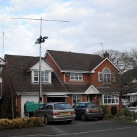
 I’ve been an addict of full wave (and partial wave) loops since realising many years ago that in comparison to a dipole, you get more bang for your buck if you build a loop – certainly you get more copper in the air – and loops are resonant on EVERY harmonic so a 40m loop will be resonant on 20, 15m and 10m. A multi-band antenna for peanuts. They will receive better too, so for a housing estate, these are mandatory.
 You will now have a structure that is effectively 20 meters tall (65 feet). Now then, the fishing pole blank will become the vertical part of an antenna which happens to be a quarter wave for 40 meter band. Being a raised antenna, we need radials and since we’re closer to the ground than a wavelength, we need a more than the traditional two radials to counteract the ground losses. We decided that 8 x radials will be about as good as 60 or so regular ground mounted radials. Do we have the maths right? We think so.
 Today, we did all the hard engineering and measured out all the bits and pieces, ready for a trial the week before CQWW. James and I laughed at the thought of how big this monster really is – and then wondered if it actually fit inside the park so as not to distrupt the walklers? Thank goodness we checked. For those of you unlucky enough to have been to our Scout Hut, you will know that when leaving our front doors, you will notice an oak tree in the distance that houses one corner of our mega-loop. James and I measured from the grass outside the doors to the last radial and we were only about 5 meters from the oak tree. Bloody hell!


 I’m currently writing an article outlining the characteristics of the Mega Loop antenna we use for Dorridge Scouts. If you would like a preview of this white-paper, please let me know.
 The Mega-Loop is working superbly at the Scout hut, although I’m trying to find something better for 160m. The impedance is already slightly low on top band and with a 4:1 balun in line at the feedpoint, it seems throws the SWR out by quite a bit. The ACOM 2000 seems to handle such a mis-match, in fact, it only trips out with a return power equating to around 575 watts. Technically, does this means that I can fire 1,000 watts up the coax and have nearly 600 watts come back to me? I don’t know – and certainly not above 1,850 anyway (UK band plans & license conditions etc). I’ll need to check.
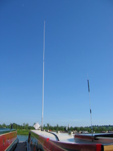 Close inspection showed that the antenna is a 2-piece 28’6″ (8.5 meter or thereabouts) white fibreglass hollow pole with a 2 foot aluminium heavy-duty sleeve at the base for mounting purposes. This main lower section (of around 17 feet or so) has three elements running the full length embedded inside the fibreglass at time of manufacture from the side feed to the top, in 120 degree arc segments. A heavy-duty male screw fitting at the top, electrically connects to the top section’s female thread.