Not being able to resist the pull of the decibals, I raided the larder tonight for a Pringle tin to build a wave-guide antenna from scrap parts. This is the story of that project.
Manufacture: I soldered a 30.5mm (quarter wave) element to a UHF bulk-head connector and drilled out a hole in the Pringle for hot-glueing. Exactly how far away from the base of the tin I should fit the element took ages – and lots of conflicting web pages. In the end, I aimed for 1/4 wave from the back of the tin. Someone is going to tell me that this is probably the most awful place to stick it – I can believe you 🙂

My multimeter couldn’t get a reading on the foil inside the can so I used kid’s water based glue to stick sheets of tin-foil to the outside. This tinfoil was grounded to the base of the tin, although I had some difficuty in doing this because there appears to be some sort of laquor applied to the base. The copper wires seen in the photo were to act as a physical and an electrical assistant; to provide a good ground to the outside of the can.
Ater connecting the Pringle-Wave-Guide to a buffalo wireless access point, I turned it in the general area of the kids room that was running NetStumbler on their network card. I waggled the can around in my shack, and went to the kids room to check if the signal strength had risen at all during the waggling. No luck. So far, it’s as much use as a dummy load.
It just goes to show that some experiments just fail.
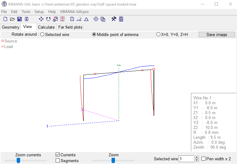 We got talking about half-squares and I confirmed that we were talking about the same thing, basically 2 x 10m verticals separated by a 20m top section. The half square is fed in one corner and according to my MMANA model, this should present 50 ohms and a great SWR curve across the whole of 40m.
 Having recently taken delivery of a Palstar AT4K manual tuner, I was keen to get her into production to replace my CG5000 in the attic.
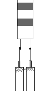 After MUCH research, I finally used about 20 feet of parallel coax feeders, connecting ladder line to both ends. To clarify, I run about 12 feet of ladder line from the ATU to the parallel RG58 cables. I soldered the ladder line to the inner core of the RG58 coax and shorted the braid-to-braid. My 20 feet of RG58 runs to the attic, through walls, up ceilings etc and in reverse, I connected the ladder line to the RG58. Again, I shorted the braids of each line to each other with a solder blob. My ladder line then has another run to the feedpoint of a large 60m loop that runs through the attic and around the garden.
 (Note, this product is at the “enquiry” level, it is not a stock part from Barenco)