
RF Weld – Click to zoom
The M0XXT Double Xray Firm had one of our outings again last weekend with myself, Tim (M0URX) and James (YOMsoft author). We built our biggest vertical yet, a loaded quarter-wave for 80 meters. Click the picture to compare Tim and I against its size. Awesome! 21 foot (6 meter) scaffold pole with 40 feet (12 meters) of SpiderBeam pole above. We’re getting an 18 meter version of this which should be great fun.
For speed of assembly on the day, we used 4 very thin strands of insulated copper wire out of a three-pair (6 way) telephone reel for the elevated radials. They’re very thin but would do the job of allowing us to raise this baby up in the air 6 meters.
The radials ended up at ground level, wrapped around galvanised tent pegs. Without realising it, we were trusting the insulation coating of the wire itself to keep the radials from being grounded. Actually, we never really thought about the consequences! Anyway, a 100w squirt proved most efficient and we achieved a 2:1 SWR curve from 3.625 to 3.750. We needed to shorten it a few more inches, however before we took it down again, I thought it prudent to fire 400w up it to make sure nothing broke down. Thump; I stuck a good carrier from the ACOM 2000 down the pipe and “pop”. The SWR pinged up to over 3:1. What had happened?
The insulation on every single tent peg had broken down in an instant and melted through to convert our careful elevated radial system into a grounded system in a flash.


")


 Having recently taken delivery of a Palstar AT4K manual tuner, I was keen to get her into production to replace my CG5000 in the attic.
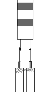 After MUCH research, I finally used about 20 feet of parallel coax feeders, connecting ladder line to both ends. To clarify, I run about 12 feet of ladder line from the ATU to the parallel RG58 cables. I soldered the ladder line to the inner core of the RG58 coax and shorted the braid-to-braid. My 20 feet of RG58 runs to the attic, through walls, up ceilings etc and in reverse, I connected the ladder line to the RG58. Again, I shorted the braids of each line to each other with a solder blob. My ladder line then has another run to the feedpoint of a large 60m loop that runs through the attic and around the garden.
 I check into the HamAntennas Yahoo Group fairly often and it occurs to me that collectively, there seems to be a lot of smoke and mirrors surrounding the design of low-band antennas and everyone seems to forget the basic principles, that low-to-the-ground antennas will form bubbles of RF above you. We call them NVIS or Cloud Burner antennas. The graphic is a plot of my home-brew 40m loop in the garden from MMANA. It’s 25 feet above the ground (which is exactly the same far-field plot as an 80m loop at 50 feet). Clearly it’s going to work well at what it’s designed for. Up to about 1,500 miles. In practice, it conforms precisely to my software plot.


