Tag Archives: 40m

DX Commander pre-production testing all-band vertical

BuyNow[EDIT] This is a very old post from about 2018..

The shop is on the link to the right, else the VERY OLD article is below:

40m-featured-image


I finally found some time this year to pull all the components together to test out in a real-world setting, the idea of using multiple elements on a single vertical fibreglass pole to achieve very good SWR and radiation patterns.

The problem with verticals is than in the main, people need either ATUs or they use that awful UNUN business with a single radial. The 9:1 UNUN business is just inefficient and the only way to to use an ATU effectively is at the feedpoint, not at the rig-end due to the severe losses.

A feedpoint ATU is expensive and generally requires a 12V power source. And long verticals have awful radiation patterns beyond 5/8th of a wavelength.

So the only way to reliably install a vertical and dispense with any worries about SWR and power handling is to build a mono-bander.

Regulars will know that I’ve been playing with the idea of adding separate elements to a 40m vertical mono-bander to add in the odd frequency, say 20m – but the interaction between elements can cause impedance issues (read SWR).

With development, I’ve discovered the optimum spacing between elements to achieve pure quarter-waves on 40m, 30m, 20m, 17m and 12m. It happens that the 40m vertical will resonate on 15m for excellent very-low radiation patterns and with the addition of a shorter-then-normal 10m element (around 2.6m in length) one can get radiation with a regular quarter-wave pattern, although the idea of using a ground-mounted vertical for 10m is slightly off-putting. There are other methods to get good radiation on the 10m band.

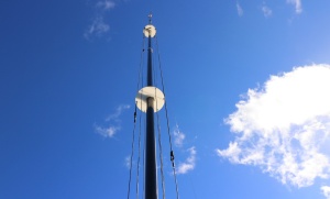
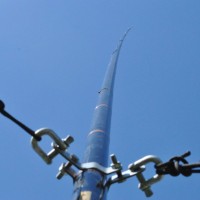
A picture speaks a thousand words, so, without further waffling, here is the prototype in action. It uses a regular DX Commander fibreglass pole which is around 9.7m in length with stainless hose-clamps using 8mm ID aquarium tubing (softened in hot water to push over the clamps). These clamps don’t scratch the tubing and securely hold each section from slipping down in a gale.

The base plate (radial plate) in the prototype is an aluminium angle with an SO239 fitted. The centre conductor is soldered with added heat-shrink and flooded with hot-glue. Connectors are used to connect to what I’m calling the “driven” plate with stainless nuts. RF enters the driven plate and self-selects the band it wants, just as a fan-dipole would. A guying point made from Nylon 66 keeps the elements optimally spaced as well as securely hold the mast upright at 1.2m off the ground to three guy stakes.

At the 5m point, a “spreader” plate houses the 20m and 17m elements on 3mm bungee cord with the 30m and 40m elements passing straight through. At the time I took the pictures, I had dispensed with the 15m and 12m elements.

In operation, I achieved better than 1:1.5 SWR across the operational bands selected. It was fun leaving WSPR mode running and allowing it to change bands without any ATU etc.

This antenna will comfortably handle 5000 Watts, although of course, the author only ran 400W RTTY for long periods for practical testing.

Hand-production of this system is extremely time-consuming so I am about to launch this with slightly lighter-weight and machined components to reduce cost. Target consumer price will be around £99. You’ll just need to add the wire and follow the instructions.

If you’d like to stay informed about progress, let me know.

Compact half-square for 40m band

I’ve just had an interesting discussion on 40m this evening with Peter, OH6GHI, also an antenna enthusiast. I happened to mention that I was listening to him on both VFOs. VFO A on my dipole and VFO B on my vertical and I found the stereo image very interesting as the polarisation of his signal to me changed.

half-square-basic-designWe got talking about half-squares and I confirmed that we were talking about the same thing, basically 2 x 10m verticals separated by a 20m top section. The half square is fed in one corner and according to my MMANA model, this should present 50 ohms and a great SWR curve across the whole of 40m.

Continue reading

Bidirectional switchable 40m wire yagi

I switched on the other evening and heard a very quiet DX caller on 7.142. It was YC0LOU from Indonesia and I could only pick up parts of his call. He called and called and had no takers. In fairness, he was extremely quiet but as the sun was gradually moving around the sky, he finally became audible and it was worth giving him a shout. 400w off my inverted V at 7m height got his attention but I needed a few blasts for him to get my call right. I put him on the cluster and he had a pile up.

Now, the point is, had I had more gain, I’d have not only heard him better, but he’d have heard me quicker too.

So I could add more height to my Inverted V but the difference between 7m and 10m isn’t actually that much at 5 degrees off the horizon – not even a db. Hardly worth writing home about.

40m-wire-yagi-drawingAnyway, this was the QSO that made me sit up and take stock of what I could do. I was seriously considering phased verticals for DX when I thought up the idea of having a switchable wire yagi. Either firing East or firing West.

Like me, you may already have an inverted V dipole up for 40m, all you need to is build another one about a quarterwave in front – or behind your existing dipole but out of a single wire. You don’t need to feed this with coax, it’s a parasitic element, like a 2 element yagi.

Continue reading

Working 15m band on a 40m vertical antenna

Note: This article discusses the merits of a 3/4 (three quarter wave) vertical -vs- a 1/4 (quarter wave) antenna.

You can build a 40m vertical quarter wave antenna and ground mount it with 16 x 4m radials and operate it at the third harmonic; 21MHz.

Actually, all my experimentation has shown that if you multiply the quarter wave resonance by 3.03, you’ll have the next available usable band. In this case, if you tune a 40m vertical to 7.00Mhz, you’ll have the whole of the 15m band to play with with a centre-point of 21.300Mhz. Oh, and you’ll still have the whole of 40m band under 1.3:1.

Now here’s the controversy:

Most people who read antenna publications or the ARRL handbook believe that if you actually make this antenna, you’re creating a cloud-burner on 15m.

Technically correct (sort of) – but for DX, wrong.

On the surface, the 10m long 40m vertical that’s used on 21.225MHz does indeed look like a cloud burner. Here it is. 15m band in green -vs- a pure quarter-wave in red).

quarter-vs-three-quarter-wavelength-vertical-antenna-plot

(click to expand quarter-wave in red, three-quarter wavelength in green)

Continue reading

3 Element 40m Vertical Parasitic Array (VPA) Vertical Yagi

Essentially, this is a single 1/4 wave vertical antenna with ground radials, complimented by a pair of parasitic verticals; a reflector and a director. It will deliver around 6db of additional gain over a standard vertical with a beamwidth of around 70 degrees. I have built mine pointing 300 degrees so that I can work the US easily at night.

I call this the M0MCX VPA (Vertical Parasitic Array).


Hours of planning and modelling with MMANA has finally produced an excellent and extremely economical method of producing gain in one direction, although the front-to-back ratio isn’t superb, it still has some rejection.  Continue reading

Converting a 40m vertical to run on 80m / 75m band

Recently, I created a slightly loaded 40m vertical with 25 ground radials. It seems to work very well although the receive noise is pretty lousy compared to my loops and dipoles, however on transmit, it does seem to work as planned; a typical 1/4 wave pattern that outperforms regular dipoles at low angles of radiation.   Continue reading

Multi-banding 10m long 1/4 wave 40m vertical antenna for 15m band

I’m always curious to discover if a mono-band antenna will work efficiently (or otherwise) on another band. I recall that when I first studied antennas, it was explained that a dipole antenna will be resonant on every third harmonic. That means a dipole for 7.1 MHz should also work on the frequency three times bigger, in other words 21.3 Mhz. Actually, experience tells me that the real resonant frequency will be a little higher.

58 -vs- 14

1/4 wave vertical for 40m band can also be a 5/8th for 15m band

Continue reading

40m Quarter Wave Vertical, Cornwall

40m vertical

Quarter Wave Vertical 9.6m in length

I’ve tried many verticals and never had good results APART from this one.

This is a 9.6m long fishing pole and the length of radiator is the same. I fixed 16 x 10m long radials to an insulator that I had lying around. I would have preferred this to have been aluminium but I already had three of these. Most of these bits were salvaged from the three-element vertical array with raised verticals that James and I made back in 2009. Each bolt was bonded together with some copper wire that is out of shot, underneath the insulator and the radials were politely scattered in an approximate radial system on the ground. SWR is 1.0:1 according to my electronic controller on the Acom 2000.

The results have been amazing but I do realise that I had two things on my side; location by the sea and almost no electrical noise. Bliss.

As I write this, I’ve worked 48 DX entities over about 7 hours operating time on 40m. Quite incredible. I’m a convert.

How to make a loop antenna for 40m and 80m bands

SkyloopI’ve been an addict of full wave (and partial wave) loops since realising many years ago that in comparison to a dipole, you get more bang for your buck if you build a loop – certainly you get more copper in the air – and loops are resonant on EVERY harmonic so a 40m loop will be resonant on 20, 15m and 10m. A multi-band antenna for peanuts. They will receive better too, so for a housing estate, these are mandatory.

When I first started out with this hobby, I had a half-sized G5RV and I genuinely thought that I’d never get onto the 80 meter band. Within 18 months, I had worked out that you can build a loop of a wavelength in circumference (give or take a percent or so) and feed it directly with coax (and a 4:1 balun). Even better was the idea of putting loading coils in each corner of a square loop and you could lower the resonant frequency by a substantial amount.

Continue reading

Footnote: 40m and 80m skyloops for your back garden

You may have a smallish back garden like me; 10m deep and 14m wide. Your 40m loop (that’s really 40m [or so] all the way around) will resonate on the 40, 20, 15 and 10m bands. Mine is only about 20 feet off the ground, around gutter height. Its not quite square but the far side and the near side are completely different lengths to make it nearly a triangle. Not quite. I have coax to the feedpoint and a cheap 4:1 balun there. With some trimming on a sunny day, you can make it work on all the amateuir bands – and I even used it on 2m once!

My 80m loop was (and still is) square at about 15m per side which is actually too small for the 80m band. My 80m loop is actually 60m all the way around. To make it “bigger”, I added 4 x loading coils into each corner. These coils are 2 inch in diameter, 6 inches long and approximately 30 turns on each coil. With some farting about, you can easily make it tune either the CW or the SSB portion of the band. If you have a tuner, you’ll dial that out easily anyway, particularly at lower power: 400 watts and under. The 80m loop happens to work on 30m band too. Just a fluke. Great for digital.

Continue reading

40m Vertical Parasitic Array Antenna Part III

Vertical Array 40 meters

We finally built the 40m array on Saturday and conducted a full test on Saturday night, in preparation for CQWW this weekend coming (24th/25th Oct 2009). The good news is that signals bearly audiable on 40m on our standard Mega-Loop came up a few db on the array, to around 5 and 7.

The front to back ratio could be higher. Germans were crawling all over us, working Worked All Germany contest which was a good test, but it did hamper our out-and-out gain tests to US. Many of them probably switching off and saving their energy for next weekend. The modelling we went for gave us maximum gain at 10 degrees take-off. We could have gone for slightly less low-angle gain and instead aimed for a very high front-to-back ratio dialing in up to -15dB off the back. As it is, this current antenna only gives us around -6 db gain off the back. There are some benefits though, like working VK “off the back of the beam”, which I’ve never said before on 40m. Great fun.

Essentially, we have the gain of a non-steerable 4-square array so we should have fun into the top end of South America as well as all of North America, right up to Vancouver and Alaska.The proof of the pudding though, is this weekend and needing 40m to work all through the night, from 7 at night through to 7 in the morning – possibly more. This antenna needs to give us 12 hours out of each 24 hour slot, a must for a Multi-Two entry. Station #2 will have 160m, 80m and 20m to play with all night.

Remember to dial your logging program to update GetScores.org. A live scoreboard is hilarious fun for teams and will keep you on your toes all weekend.

Good luck and have a blast.

C.

40m 3 Element Vertical Yagi Antenna – Part II

We’ve built some large antennas before but never this big; a 3 element 40m vertical array with raised radials. We made it a raised radial system for a) a quick match to 50 ohms and b) it needs to be a “field” system. We can’t permanently leave our antennas in a public park.

First, you need to get into the scaling to believe it: Take a 6 meter scaffold pole of 48mm diameter (21 feet x 2 inch). Stick it upright on the ground and sleeve inside it, an inch and a half (30mm?) 4 meter (13 feet) pole. On top of this, sleeve a 10 meter (30 foot) fishing pole blank.

Sleeved Scaffold Pole AntennaYou will now have a structure that is effectively 20 meters tall (65 feet). Now then, the fishing pole blank will become the vertical part of an antenna which happens to be a quarter wave for 40 meter band. Being a raised antenna, we need radials and since we’re closer to the ground than a wavelength, we need a more than the traditional two radials to counteract the ground losses. We decided that 8 x radials will be about as good as 60 or so regular ground mounted radials. Do we have the maths right? We think so.

The radials have been modelled at 10 meters length each since they are essentially part of the circuit and will have currently on them, hence the quarter wave dimension. They slope to the ground at approximately 45 degrees. We need to attach some paracord to the ends of the radials and extend them down a further 7 meters before we finally hit the ground. Imagine how far away you are now from the original scaffold pole? I can tell you, it’s 13 meters (42 feet). The diameter of just one of these then spans 26 meters (84 feet) and we have three laced together at a spacing of 10 meters each (three element array).

40m Radial System Today, we did all the hard engineering and measured out all the bits and pieces, ready for a trial the week before CQWW. James and I laughed at the thought of how big this monster really is – and then wondered if it actually fit inside the park so as not to distrupt the walklers? Thank goodness we checked. For those of you unlucky enough to have been to our Scout Hut, you will know that when leaving our front doors, you will notice an oak tree in the distance that houses one corner of our mega-loop. James and I measured from the grass outside the doors to the last radial and we were only about 5 meters from the oak tree. Bloody hell!

We’ve had to re-engineer where we had planned to fit this monster into the park since it has a total wing-span of 52 meters (170 feet).
A picture tells a thousand words, so feel free to check the pics.

40m 3 Element Vertical Yagi Antenna

We’re putting together a Multi-Two entry for CQWW this year and it’s pretty clear from our experience with CQWPX that we not only need gain to the US on 40m but we need excellent front-to-back ratio. A new antenna was required.
A two element yagi was considered but we don’t have a tower for such a beast. We did though have various 10m fishing rod blanks and a load of aluminium scaffolding tubes. With some analysis, we feel we can build a high gain array utilising Yagi’s principles of a driven element in the middle and a reflector and a director element front and back.

Original modelling was conducted with MMANA however, the team has recently started to convert to modellilng with NEC2. James’s NEC model confirmed my 5db gain using MMANA at 10 degree take-off angle.

40m Three Element Vertical      3d Far Field Vertical Yagi     40m Far Field

The feedpoint for each element will be at 9 meters above ground using 6 meter scaffold pole sleeved with a 4 meter inch and a half steel pole. The 10m Sky Blue Leisure flag poles sleeve to the inch and a half steel poles. I’ll take some pictures tomorrow of the build.
Make no mistake, these will be monsters with 8 raised radials per element. Today, I made the insulated guying blocks for the radials. This is going to wipe the floor!

Watch this space.

Helically wound 40m vertical

Helically Wound 40m vertical
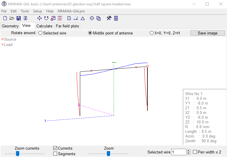
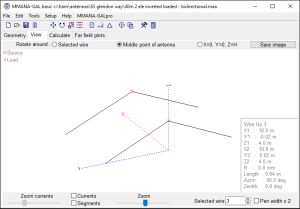
Chris (G0EYO) kindly modelled my 40 meter vertical with loading coil (https://www.m0mcx.co.uk/?p=44) and mentioned that he felt the take off angle may be higher than I would like it.. He suggested experimenting with a helically wound vertical. Chris recalls a team event last year where they needed to get on 40m fast so a fishing pole and about 10 meters of wire were produced along with 2 elevated radials. The problem was that the fishing pole was only about 7 meters long. The team simply wound the 10 meters of wire on to the fishing pole and hit the TUNE button on the rig to swallow up any mismatch.

I tried the same experiment with my 8 meter fishing pole and 10.6 meters of wire. Why 10.6 meters? Simply because I cut the wire a bit long intentionally. Using 4 elevated radials, I found the resonant 1:1 frequency with a near 50 ohm match was 7.7 Mhz. Way above my requirement however the SWR bandwidth curve was very strange with a flat 2:1 SWR all the way from 7.2 Mhz right up to 7.6 Mhz. Indeed, the TUNE button easily swallowed the incorrect size of this antenna for the whole of the 40m band. I needed to make this longer though so I could run high power in a comfortable manner.

Stripping off the 10.6 length, I found a 100 meter roll of 6 core telephone wire and chopped 15 meters off it. I wound this on to the fishing pole which gave me 6.8 Mhz. A couple of attempts later and about 50cms of wire short, the vertical tuned in to 7.05 Mhz with a very large bandwidth, certainly better than the loading coil version.

Later in the evening I heard VE1KF managing a European pile up from his QTH in Nova Scotia. My vertical broke the pile in one shout. He emailed me later, “Your signal was a nice strong 59“. Thanks for the report Brent.

I give a thumbs up to this antenna; I believe I am getting a lower angle of radiation. It’s the best 40 meter vertical I’ve made yet but remember – these only work from about 1,000 miles upwards. If you want lots of QSOs, you’ll need a dipole or a loop to compliment this.

More pics: https://www.m0mcx.co.uk/gallery/index.php?/category/40

Postscript: I recommend using a 1:1 choke balun on this design to stop the feedline radiating and to ensure that all the RF goes where it should. See here http://www.hamuniverse.com/balun.html for some regular designs.

73, Callum.

Shortened / loaded 40 meter dipole for attics

This morning, I removed from the loft, a pair of nested dipoles for 40 and 20 meters fed with one coax feeder. The 40 meter dipole was loaded with some coils so that I could fit it in the attic.

It gave me 40, 20 and 15 with a push because although a 40 meter dipole should give you a resonant 15 meter antenna, in this case – with the coils for 40 – it mucked the maths up and caused the ATU some trouble. On 40m, it worked a treat.

If anyone is interested in making up the “shorty forty”, you may find my experience of interest: Each coil was made from 3 meters of hard drawn BT downlead, coiled around a PVC plumbers pipe of around 25mm diameter and about 30 turns or thereabouts. The actual spec from the dipole centre was as follows:

  • Dipole centre to coil: 3.7 meters
  • Coil to end of dipole leg: 3.3 meters
  • = 7 meters each leg + length of the coil

I replaced the nest was replaced by a half-size G5RV in a “lazy” inverted V configuration, tucked up in the rafters. Good for running a second radio and it gets me on 10m as well as the WARC bands.

Incidentally, when I was testing this original dipole, I started off with 8 meters for each leg and ran it through the MFJ analyser. It was resonant on 6.66 Mhz. An old favorite pirate band that some people may remember. Adding the coils raised the renonant freq from 6.6 to 8.5, so cutting a meter off each side to get the whole thing working for the amateur bands was necessary.

So there you have it, a 45 foot long 40m band dipole.