All antenna love a bit of height.
Here’s a fun video:
All antenna love a bit of height.
Here’s a fun video:
Here’s a really simple way of double checking how to much to trim your antenna elements.
You only need to type in the numbers in the Cyan boxes.
Just type in where it is resonant right now – then type in where you would like it to be resonant and the spreadsheet will auto-calculate the trimming.
* Thank you to Aubrey (AubsUK on YouTube) for the Online version below:
WARNING: This post has been replaced with the following analysis and design:
Banana Antenna Design May 2017
– – –
The Resonant Feedline Antenna is also known as:
• Sleeve Dipole (& Flowerpot Antenna)
• Resonant Feedline Dipole (J Taylor, W2OZH)
• Tuned Transmission Line Trap, T2LT (CB folks)
For more about common mode chokes, see this article:
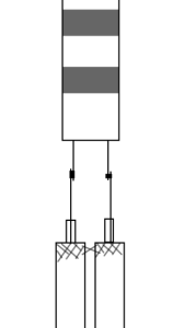
Pictures of this experiment follow including the 10-25 MHz >8K choke follow.


Coax Transmission line coax stubs are frequency dependent. Making a stub for one frequency means it WILL NOT work for another frequency. My example is for a 20m Resonant Feedline Dipole, sometimes called a Sleeve Dipole or Resonant Coax Dipole or Tuned Choked Coax Dipole.
So you have an approx 75 ohm impedance antenna and you want to get the best match you can. Take the wavelength of the frequency, multiply it by the velocity factor of your 75 ohm matching coax and multiply again by 0.0815.
For example.
14.225 MHz = 21.089 metres
21.089 * 0.66 (what ever your velocity factor is) = 13.19
Multiply 13.91 * 0.0815 = 1.134m
Therefore, your transmission line coaxial transformer will be 1.134m long which is apparently about 29 degrees around the 360 degree circle.
Data found here: PA0FRI page.
Finally, I discovered MANY pages on eHam and QRZ forums of people asking the same question but most answers are with people answering questions which were not asked – or giving advice how to fix the antenna, or live with it. Why Americans need to argue the toss when others just need answers beggers belief 🙂
 Having recently taken delivery of a Palstar AT4K manual tuner, I was keen to get her into production to replace my CG5000 in the attic.
Problem: the route to the attic from the shack is complex but I have a number of spare coax runs going that way including a couple of RG58 cables that I installed about 10 years ago as backups. Actually I originally installed three RG58 lines but I’ve been using one of them to send 12V up the line to the ATU.
 After MUCH research, I finally used about 20 feet of parallel coax feeders, connecting ladder line to both ends. To clarify, I run about 12 feet of ladder line from the ATU to the parallel RG58 cables. I soldered the ladder line to the inner core of the RG58 coax and shorted the braid-to-braid. My 20 feet of RG58 runs to the attic, through walls, up ceilings etc and in reverse, I connected the ladder line to the RG58. Again, I shorted the braids of each line to each other with a solder blob. My ladder line then has another run to the feedpoint of a large 60m loop that runs through the attic and around the garden.
The results have been quite amazing. Comparing my 40m reference dipole to the the CG5000 (SG230 type) ATU feeding the 60m loop has always shown that the loop was about an S point lower than my reference dipole for most stations.
10m and 15m nested dipole
Last year, with the assistance of Stu, M0NYP, I built a fan dipole out of D10 military telecoms wire for 80m, 40m and 20m for club field days. There was a fair amount of gap between each element, probably about 5 to 7 degrees becasue that’s what I thought you should do. For those people who came to either the Avoncroft Mills on the Air day, or the SSB Field Day, will recall the antenna. However, we lacked 15m and 10m though which I found a disappointment.
To become “all band”, I considered adding more elements to the Field Day antenna but experience has taught me that multi-band wire dipoles have a tendency to get tangled in the field. Adding more elements would probably just mean more tangles = less fun. In a Field Day situation, that’s a frustrating day out.