My other recent article discusses our XXT Loop that relies on three very high trees equally placed as an equilateral triangle would be. Initially, my design focussed on a 2 wavelength loop for 80m. This required not only a serious amount of high quality copper wire but some extremely capable trees!
Cutting the design by half had some advantages, namely I needed only 80 meters of hard-drawn copper wire instead of 160 meters and I could trade off the whole of the scout field into something a little more manageable – three trees nearer the shack! Luckily, I recently found 600 meters of high quality enamelled antenna wire going for a song (eight quid actually!) which has assisted this experiment 🙂

Anyway, I drew this to scale using Google Earth and Paint Shop Pro and had my Cubs measure the trees one night as part of a badge (very satisfying!). It turns out that these trees are in the 85 to 100 feet feet category, the real Daddies of the local Oak Trees! Of interest, if north is “up” and the feedpoint is over on the far right, the major gain is over to the north west area (WNW to be precise).
Getting rope over the top of these trees was a real test and over the last few days I’ve been doing some major development work into designing something that will reliably shoot a fishing wire over the top of these. May I say now that once I had perfected the “gun”, it is certainly one of the most satisfying and exhilarating events to shoot a weight over the top of a 100 foot tree watching tens of meters of fishing line fly off every second as it lofts over its target. An amazing experience to have it all finally working in perfect unison.
I can hardly bring myself to tell you the precise details of how you can achive this since it cost me not only a few pennies in wasted fishing reels but many frustrating hours (days!) with various contraptions before I hit the nail on the head reliably every time. I know you can buy such “guns” in the USA, however if you really want to accomplish this on a home-brew front, you can either email me with a very grovely email or buy me copious amounts of beer in the local pub to extract the truth!

Since a picture paints many words, I’ve attached pictures of both failures and successes. In the catapult / fishing reel ONLY picture (the first one), the line is essentially too close to the catapult and upon launch, it snaps all too quickly or jerks the weight down to the earth immediately.
Using the extended fishing rod though means that the line is longer which takes up the initial jerk much better as it all takes off. The breaking strain is critical. Too low and it snaps, too high and it’s too heavy and doesn’t reach its target.
Finally the weight. I found that in most cases, a single 10mm heavy stainless nut was suffice. However late this afternoon, a particularly high tree was proving extremely difficult. I needed the projectile to travel further and ended up moving to three 10mm nuts. Exerting as much force as I could muster (more than ever before) I launched the three nuts at the top of the tree and whooosh, it all went over. Extremley satisfying since had I got that wrong, I could have easily crushed a finger or have the nuts fly off into the countryside somewhere. Quite worrying actually, all that force going wrong (indeed having my nuts flying off into the countryside would also have been worying!).

Of course, once the nylon line is over the tree, one has to track it down which easier said than done. Walking around a field looking like a dancing fairy with arms out-stretched to find the line has the locals glaring hard – but the most effective. I tried lacing ribbons and coloured string to track the projectile but this just caused jams and further problems.
Once found, attaching a strong cord is the next battle. Luckily, I have studied knots keenly over the last 18 months to become the district knot champ, however I soon learned that having a knot that would actually undo under pressure was best, not only for the weight on the line but also for the cord. The last thing you want is a stuck weight or cord up a tree. Before I worked this out, I lost about 50 meters of line in a tree in smaller increments. It glistens most interestingly in the sun. I only hope it breaks down and disintegrates next summer because the thought of it up there is most embarrasing. In the end, I discovered that applying small amounts of duck-tape so that in the event of a stuck line 100 feet in the sky, a hard pull would allow the weight to drop to the ground and the line to spring free. It’s a better solution.
I recently found some genuine American paracord from a supplier on eBay. It’s not cheap but it’s very strong and doesn’t seem to stretch much. I bought a 200 meter run. It has a 500 pound breaking strength so I’m guessing half that is a safe working load. Basically, if I can pull it with all my might, I’m happy. Attaching the line to the cord and pulling it over slowly normally did the trick – well, most times. Sometimes it doesn’t want to play so I discovered the best method of attaching my lines to my paracord to reduce that issue. I’m not telling you which method I discovered since that’s worth another pint of local ale!
Finally this afternoon, I am left with three trees with paracord running all the way up, all the way over and all the way down again. I’ve tied them off using step ladders so the local youths don’t muck with them.
Tomorrow is antenna build day. Wish me luck. I’ll let you know how I get on.
Post Script: Good news, the antenna worked a treat, see: https://www.m0mcx.co.uk/?p=138
73,
Callum.


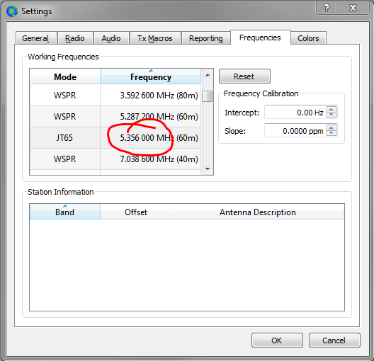
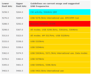 5.298.50
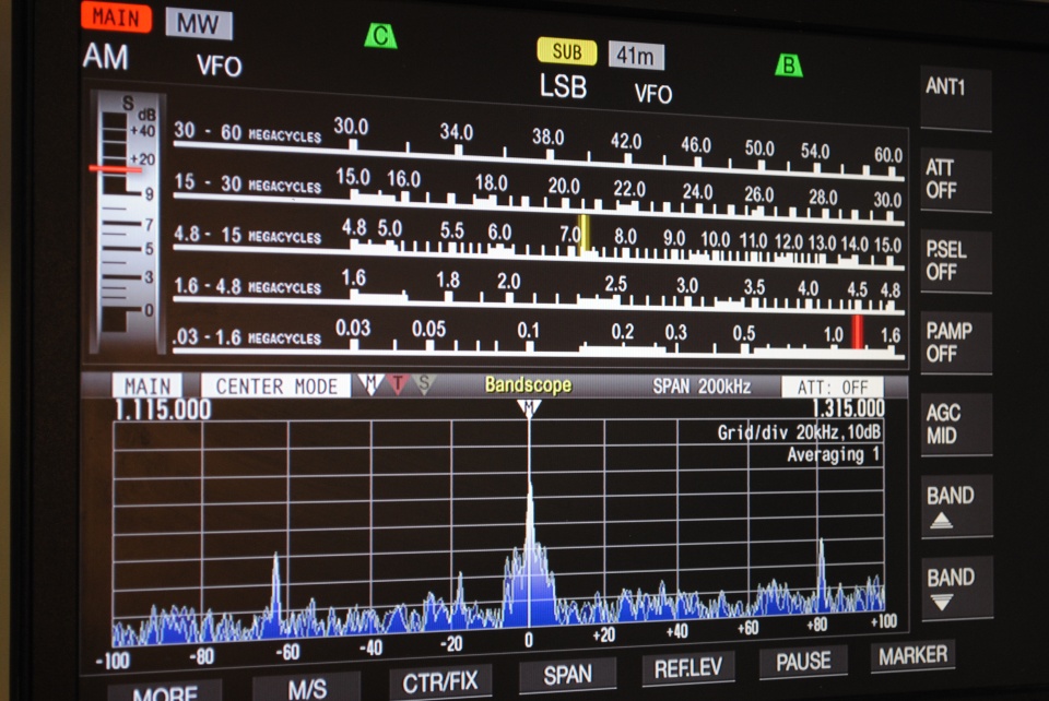
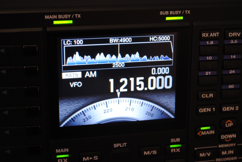
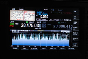 Had a ball with CQWW this weekend putting just over 1,000 QSOs in the log. 10m was very busy. The band scope on the TS-990s radio was extremely full with hardly a gap from 28.300 to 29.000 (and some!).


 I always fancied a low-angle vertical for 10m band and after doing my research, came across the Solarcon Imax 2000. It was a toss up between this, a Sigma 4 copy or the Sirio 827. The Sigma 4 is now called the Sirio Vector 4000 and I discounted this one because of the size of the radials which seemed excessive for my plot , Same with the Sirio Vector 4000 which is just too tall. Even so, the Sirio Imax 2000 is still 24 feet in length. But read on, it’s actually fairly stealthy for such a tall antenna.


 Field days seem to whoosh by in a seamless tirade of bodily abuse that starts in the balls of the feet, grows through your hands and wind blown cheeks before reminding you that you are starving hungry and you’ve only just taken over the driving seat.
 James (M3YOM) has just emailed me after discovering something worse than fitting 90 or so PL259s last week; it’s winding quadrifilar wound toroids. Pictured is a completed L1 winding for the 40m filter. He says that it’s a T130-0 core with 7 quadrifilar windings which should give around 3.96uH and there are two in the filter box he’s making from a kit supplied by Bob Henderson.
 My thanks to Lee (G0MTN) James (M3YOM) Terry (G4MKP) and Aidan (M6TTT, Scout) for getting our new station on the air for a first-time-out on WPX.

 107 in the log. I’ve no idea what my score was since I used N1MM’s DX Serial Contest template to do the logging and the miscellaneous field for logging random text did a hopeless job of being able to edit long club names efficiently.
 I’ve been lucky enough to purchase 100 meters of Ecoflex 15 recently and the solderless connectors are awesome.
 Arriving at the site on Lunchtime Friday, I got the tent up in a complete hurricane. Stripped to my shorts and a T-shirt in the driving wind and rain and all on my own, at one point I just burst out laughing at my predicament. The only thing that kept me sane was the knowledge that some other crazy people in other parts of Europe were also following my example and getting their stations worked up.
 Massive success this year with the new antenna, generating huge pile-ups world-wide. We shall never go near 80m again for JOTA. 20m is the band that synchronises extremely well with passing Scouting messages around the world, particularly if you have a technically proficient station and crew.
 RF was via one of our FT1000MP radios and amplified by an ACOM. A pair of Dell PCs running N1MM did the logging. We networked the PCs for disaster recovery purposes and used the second copy of N1MM on the spare PC a couple of times when RF shut down the run machine. We were Multi-Single.
 I personally had a couple of exceptional highlights that I’ll remember for a while. The first was on Saturday evening, running a split to the US on 40m and getting a pile up for my money. The rate meter peaked at 230 which I thought was pretty darned good. At one point, I burst out laughing with a mixture of adrenaline rush and terror! I have never had a high-gain antenna to the US and just didn’t think that it was possible to have so many people calling you! Getting spotted by W3LPL made it worse (or better..!!).
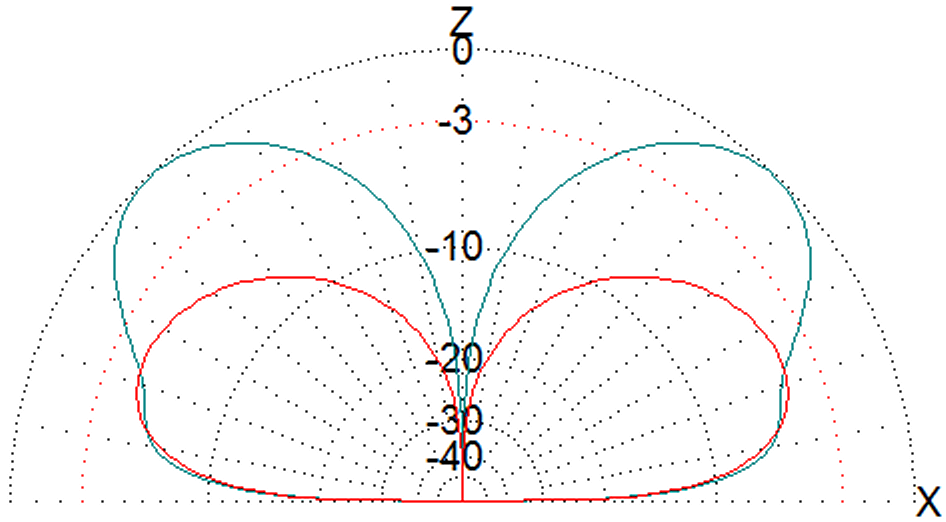
 Saturday / Sunday saw us tear down the minutely designed and executed 28.5m leg triangle and on the spur of the moment, we put one up twice the size. It only JUST fits at 57 meters each leg, and again this is a perfect triangle. At 20m in height, we should have experienced nearly 15dBi towards North America and sure enough we ran a string of US stations all Saturday and Sunday scoring on both days into California with signal reports in the 57s and 58s. Exceptional. But these lobes don’t just work into US, we worked Ethiopia, Brunei, Bermuda, VK9, the list goes on and on. This is a serious loop and great fun for running on – it’s also nearly invisible!