 If you’ve been keeping up to date then you’ll know that I have chosen the TS-2000 as the primary radio on board our new narrowboat, “Wherethehell-Rwe”. At the helm (which is a dead give-away for my yachting heritage) I have specified the RC-2000 which should be rather fun to muck about with as I swan along at 3mph across the countryside. In English then, the TS-2000 will sit at the front of the boat near the bow and 60 feet away at the stern (the back.. or in narrowboat terminology, the steering position), I’ll be running an RC-2000 remote controlled head, remote microphone and remote loud speaker. Clearly I’ll also need a switching system up near the front so that I can also use my toys in the evening in the comfort of the boat.
Isn’t this a bit over-the-top, I hear you ask? Oh yes. For those visitors to the site who haven’t seen a narrowboat, they are the long, thin steel boats that sail the inland waterways and canals of the British Isles (they used to be made of wood). The canal system was started literally hundreds of years ago and squeezes through the cities of England, Scotland, Wales and Ireland. Clearly running a bloody great big HF antenna is completely impractical, which is exactly why I’ll hinge my Shakespeare Marine HF SSB vertical over to rest when we’re motoring. However I have purchased a small 4-band 10/6/2/70 antenna that will allow me to play CB, 10m, 6, 2, 70 and PMR446 from my steering position. This antenna pulls-n-lays so that we can crouch under trees and bridges as required. Of interest, modelling my Shakespeare 5300 HF antenna whilst it’s actually lying flat to the deck, does demonstrate a small RF bubble of around -15dbi for the low bands. This will mean I can make some contacts on 40m and 80m as I travel along. Thank goodness for a high-power CG5000 ATU that has just arrived that will couple the HF antenna to my radio for an all-band experience (http://www.hamradio.co.uk/acatalog/Am_TunUnits_MyDEL.html)

I had seen pictures of the RC-2000 on the internet and I always thought it was about the size of three cigarette packets. I was about 40-50% too big. It’s more like one and a half packets sitting end-to-end (maybe a whisker more but I’ve stopped smoking so I can’t judge too accurately!). It’s smaller than you imagine because you don’t often see marketing literature or google images with the RC-2000 in situ with another item like a microphone or something.
What’s in the box? You get the head itself and a pretty external speaker that matches the size of the RC-2000. The speaker is very well made and the sound is good, peaking strongly in the 300-3000Hz band for clear voice comms. Three main cables come with the box, a large microphone extender that has a CAT5 joiner near one end connecting a female and a male 8 pin mic extension together. I don’t know why they’ve done this? Maybe so you can squeeze the CAT5 plug through little holes in your vehicle? Frankly I’ll be cutting this part off and replacing with something properly grounded. You also get an external speaker lead and a 4 way control lead. It says in the manual that one end is a 4 pin RJ45 style socket and one end is a 6 pin, in fact this is slightly misleading. The 6 pin doesn’t have 6 pins – it has 4. However the confusion reigns because it’s the size of a regular 6 pin version but the two outside slide connections / pins are removed completely. The pin-to-pin layout essentially transfers all pins on the 4 pin plug to pins 2, 3, 4 and 5 of the “6 pin plug”. If you have come here from a google search, I trust you can work this out! You also get a bag of screws, three clip-on ferrites and a large beefy TS-2000 Mobile bracket. Lastly, don’t forget a neat mounting bracket for the RC-2000 and the remote speaker.

The initial fears of the size issue soon disappear when you plug everything in and switch it on. Menu 00 (Brightness) and menu 59 (Contrast) work here for both the head and the TS-2000 at the same time, so you may have to enter a compromise situation, particularly on the brightness – however you can program different “users” and each user can have a different requirement so whilst using the main unit, you can select user 1 and when using the remote, you can select user 2 (for instance). I was initially extremely disappointed to start with because I couldn’t fathom out how to increase the contrast until I hit upon the idea of menu 59. Working these two menus mean that you can get a really clear and cute display on the go.
Using the RC-2000 itself is very intuitive with lots of neat stuff tucked away. I won’t give you a complete run-down because that would be extremely tedious however be assured that I was up and running in seconds. Apart from the soft switches down each side and across the bottom, you are left with three control knobs; the main VFO which doubles up as a finer VFO by pressing once, then the twin squelch and volume controls which mirror exactly what the main TS-2000 does.
The soft switches work well. Bottom left is initially called A-1. Pressing it repeatedly changes the functions of the bottom buttons via deeper menus, A-2, A-3, and A-4. Holding it down for about a second gives you the B series of menus as described and finally holding it down again gives you the C series of menus. Inside all these, you are mirroring the functions on the TS-2000 in various ways.
Essentially, everything that you can do with the TS-2000, you can do with the RC-2000. I’ve had mine sitting beside me for 24 hours now, forcing myself to use it for everything from changing power settings through to recalling memories. It works well – and just for fun, I called QRP into Russia on 10w and scored a hit. Why QRP? I just thought it might be an idea. Don’t worry, I’ve gone off the idea already!

My only concern is the main remote head VFO and this worries me for two reasons. Firstly, in terms of pure usability: You can tune in 1KHz steps, so let’s take the 40m band.. One clockwise mini-click on the remote VFO takes you from 7.050 to 7.051 (there’s about 30 clicks per rotation). However, you can hear a station in between these two frequencies, so you need to tune to say 7.050.50. To do this, you need to hit the VFO like a switch and a small “TUN” legend comes up on the display. You then rotate and mini-click your way from 7.050.00 up the required frequency in steps of 10Hz, so that to get from 7.050.00 to 7.050.50. You’ll need to rotate the knob around about one and a half rotations (50 clicks) to get to 7.050.50.
However, the UP/DOWN keys on the microphone is a heck of a lot faster so if you’ll be running the stock mic, you can NET someone in perhaps better by using that.
The second concern is the quality of the remote VFO knob. It feels a bit cheap, perhaps fiddly but I’m spoiled with a number of FT1000 variants in the shack here and of course the TS2000. To be fair, there’s an element of chalk and cheese here – after all this is a remote head is extremely economical, attractive and functional – and fairly unique in the amateur radio market, it’s not a snap-off, it’s an additional piece of equipment that will either extend your shack in your home to perhaps a different room or to another wall in your shack. Of course, most will buy it for mobile work, and what a beast that would be? You only need to add SGC’s 500 watt amplifier and a CG5000 800 watt PEP auto coupler and you’ll be mobile QRO all-band for under £5k! Oh! You’ll need an 8 foot stainless whip 🙂
Marks out of 10? Well I was expecting to give this an 8. I really was. I thought it would be too big – and a display that needed some “imagination” to make the best out of it. However now that I’ve had it on test for 24 hours, I can honestly say that it’s now giving it a 9, only losing points on the VFO issue that I’ll probably get over in time anyway.
Go on, treat yourself – they’re great fun.
Callum.
 The day itself was excellent; we had a different Brownie pack through the door every half-hour. Each pack would have a fun chat outside by me before watching the “Hello” film from the ARRL. It’s very American but I can’t find anything short and to the point that can replace this wonderful little blast of interest for children. RSGB, if you have something – please let me know since I would love to show something a little more English.
 Five years after becoming licensed, I’ve finally got around to putting a formal station earth / ground in situ comprising 2 x four foot copper rods and a liberal amount of copper wire into the ground on the front lawn. Instead of cutting the last 8 foot off, I used a lawn edger and shoved the copper about 4 inches into the lawn until there was two foot left. Looking around wondering what to do with this, I spotted my massive hammer drill with 24 inch 20mm drill bit. Clearly, it was asking me to drill a hole into the lawn and shove the remainer into it! I did. So I now have 2 x four foot and 1 x 24 inch ground. No idea if this remainder will do any use at all. You never know.
 Ideally, you need 12.5 kHz channel selection starting from 446.006.25 which all Kenwood’s do (eg TS-2000 and Kenwood handies) however I don’t believe there’s a way to do this with FM only Yaesu Ham rigs.
 Apart from the noise factor (loops are quiet), the vertical seems to make a better impact on transmit more often than not for DX, unless I’m into NVIS or near NVIS (500 miles or so). Even then, up to 1,500 miles, the jury is out – either antenna can win. Beyond 1,500 miles the vertical seems to do a better job most of the time – not always, however my loops are very low to the ground, maximum height of 7 meters. On 40m, I would say the vertical is a better antenna to have almost all of the time unless you need NVIS for local copying – and with the sun spot cycle as it is, you won’t get this for a while yet!
 Now.. This is a very different animal to the Skyloops that most people build. If you want a pile-up generator, this is the animal to have. It fundamentally, takes all your RF energy and pancakes it low to the ground in various star shapes. Very Of course, you will sometimes null out the station you want but you could get really clever and change feedpoints with relays. But ignoring the clever engineering, this has changed my mind as to the effectiveness of a high skyloop.
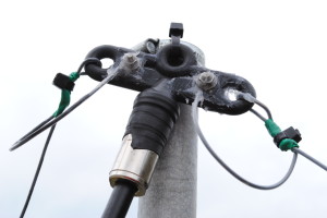
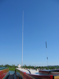 Close inspection showed that the antenna is a 2-piece 28’6″ (8.5 meter or thereabouts) white fibreglass hollow pole with a 2 foot aluminium heavy-duty sleeve at the base for mounting purposes. This main lower section (of around 17 feet or so) has three elements running the full length embedded inside the fibreglass at time of manufacture from the side feed to the top, in 120 degree arc segments. A heavy-duty male screw fitting at the top, electrically connects to the top section’s female thread.
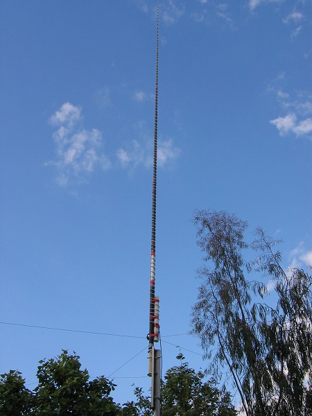